Step by Step Assembly
Disclaimer
When building and working with OpenSPIM it is your own responsibility to make a risk assessment before starting any procedure and on the basis of the risk assessment to make sure appropriate safety precautions are taken to avoid damage to any person or property.
Inform yourself about the manufacturers instructions for all parts used for the openSPIM before you start assembling the OpenSPIM.
Follow all instructions in the manufacturer’s operator’s manuals, especially the safety precautions.
We take no liability for any personal or property damage caused by the openSPIM or any parts described on this page.
Warning: Depending on the laser class of the laser, the laser beam or even scattered light from the laser may be extremely harmful to eyes and skin. Some lasers can potentially cause blindness after direct eye contact.
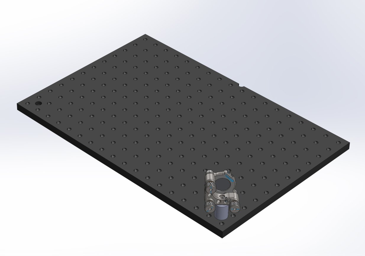
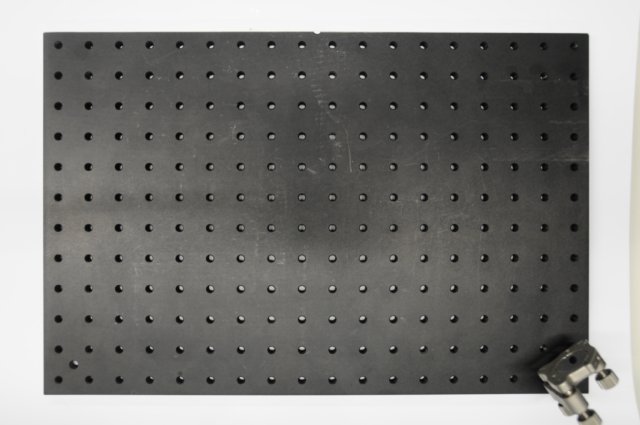
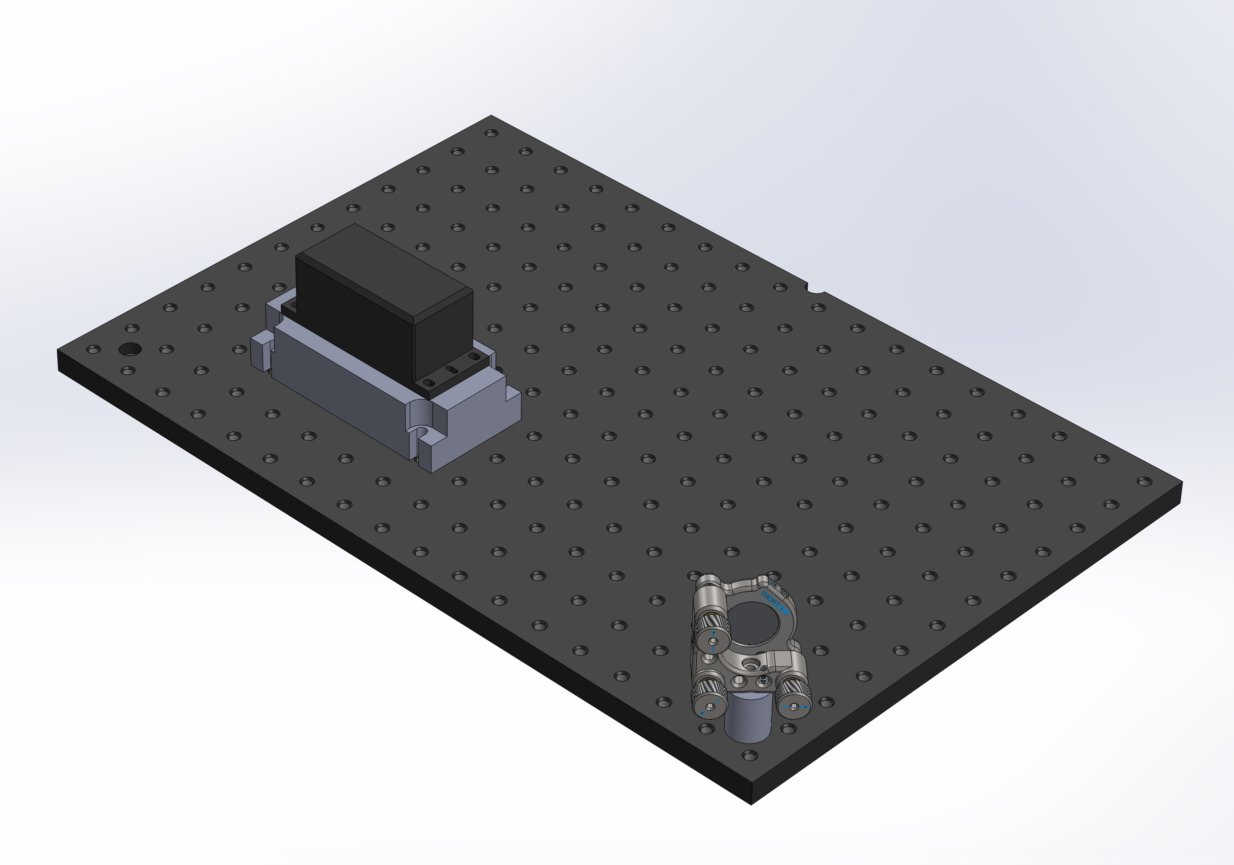
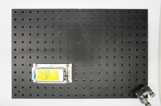
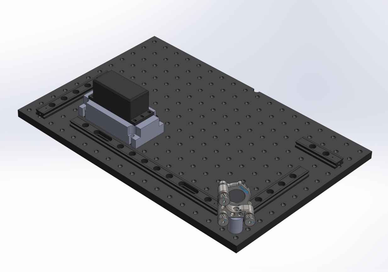
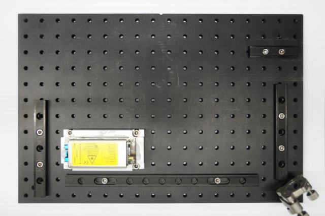
Before you start to assemble please make sure you have all needed parts or you know how to improvise them. The light path of our original design is 50 mm off the top surface of the ThorLabs metric optical breadboard (part #: MB3045/M) where everything is installed.
The optical breadboard has a length of 300 mm and a width of 450 mm, with a grid of 12 x 18 M6 threaded holes spaced 25 mm apart from one another. We will use a coordinate system similar to a spreadsheet (like OpenOffice Calc or Microsoft Excel) to make it easier to know where each component and cap screw is positioned. Starting with A1 in the upper left corner (as seen in the images), and ending with R12 in the lower right.
Please also forgive the confusion about the Youtube videos and the corresponding images, the documentation was done in two different locations months apart from each other and small design changes happened in between.
- Assemble purchased components
- Install assembled ThorLabs components on rail carriers
- Install illumination axis on the optical breadboard - Part 1
- Alignment of laser
- Install illumination axis on the optical breadboard - Part 2
- Install detection axis on the optical breadboard
- Install the 4D motor system
- Install cables and connect computer
There is a short introduction to the optics of a SPIM available as the SPIM Optics 101. This will also give practical hints for optics alignment and laser safety.
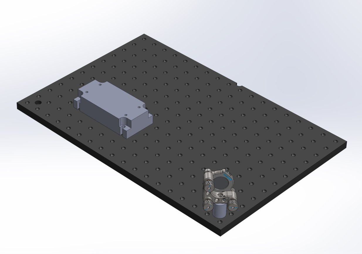
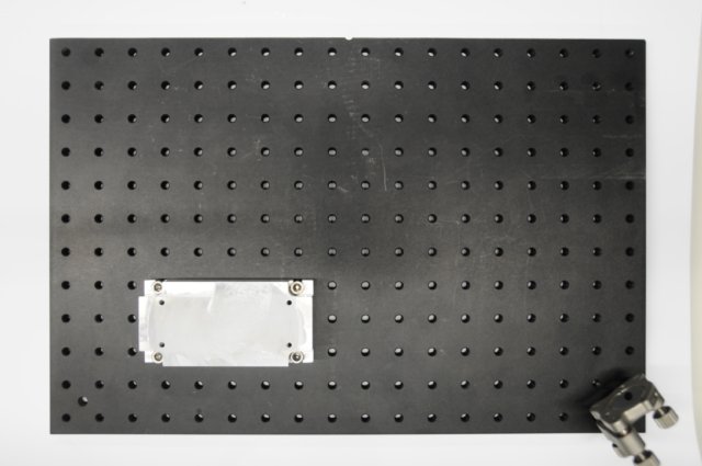
Assembly overview
OpenSPIM buildup SolidWorks and real
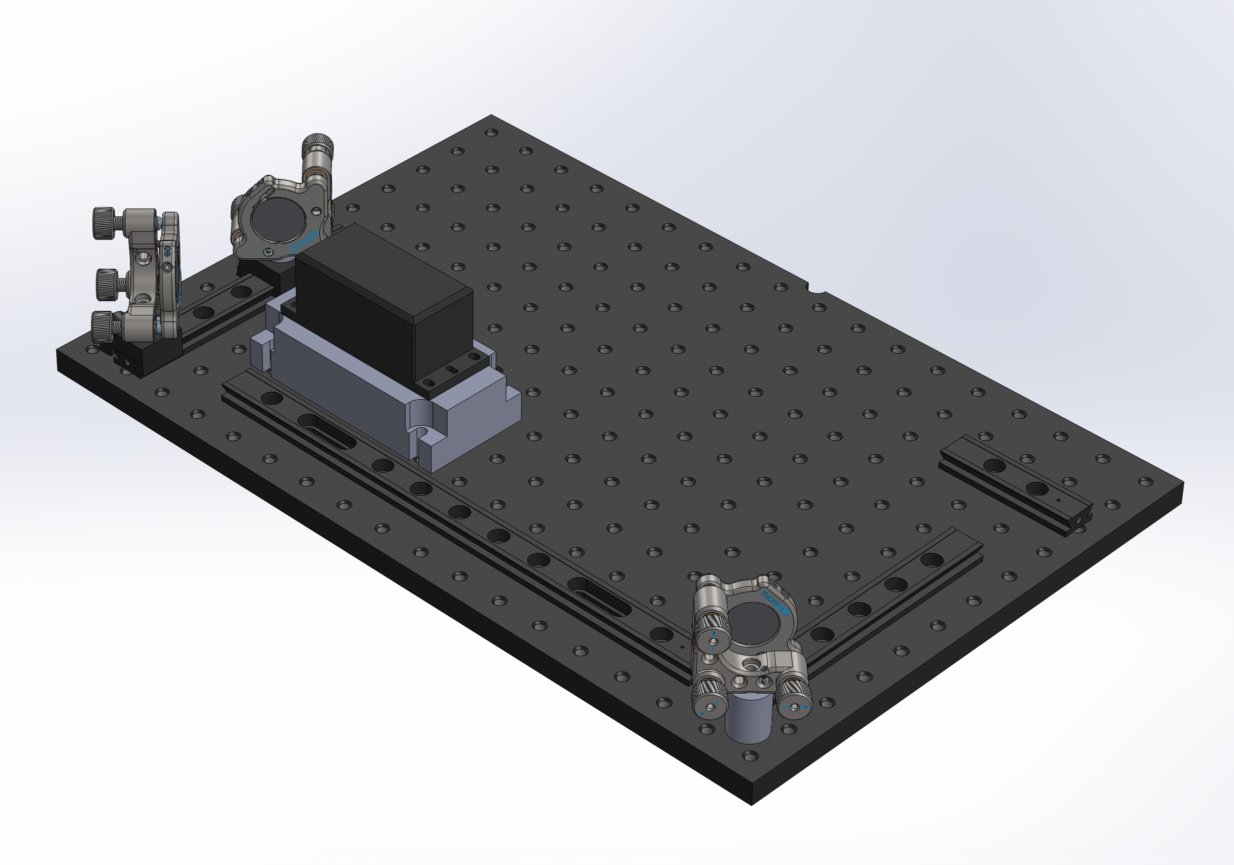
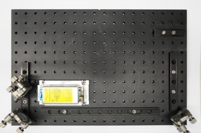
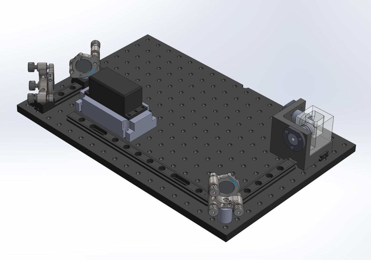
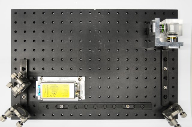
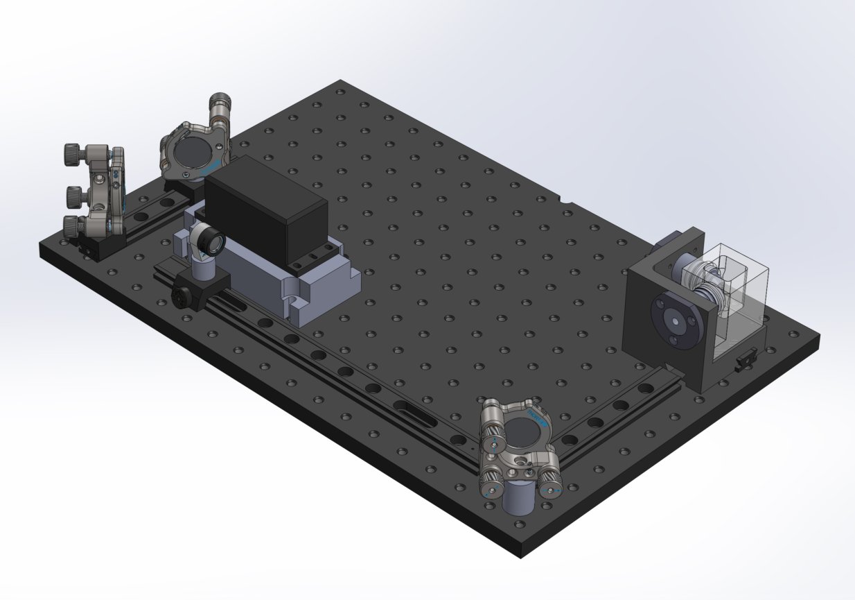

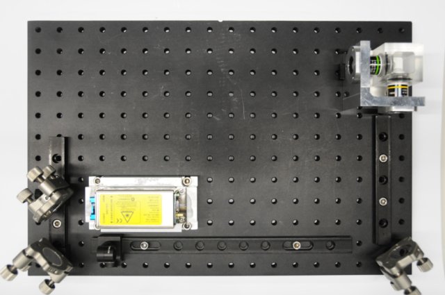

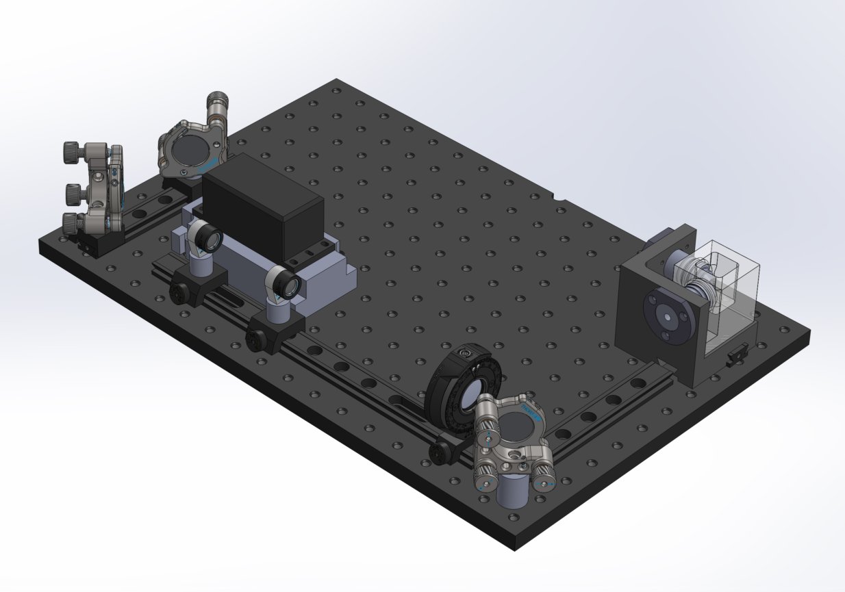
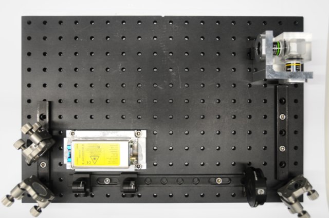
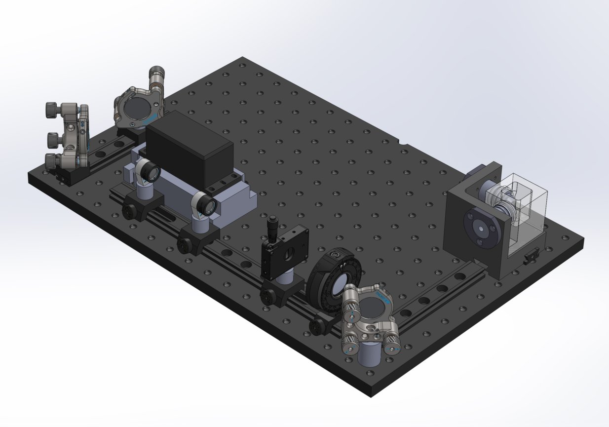
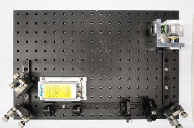
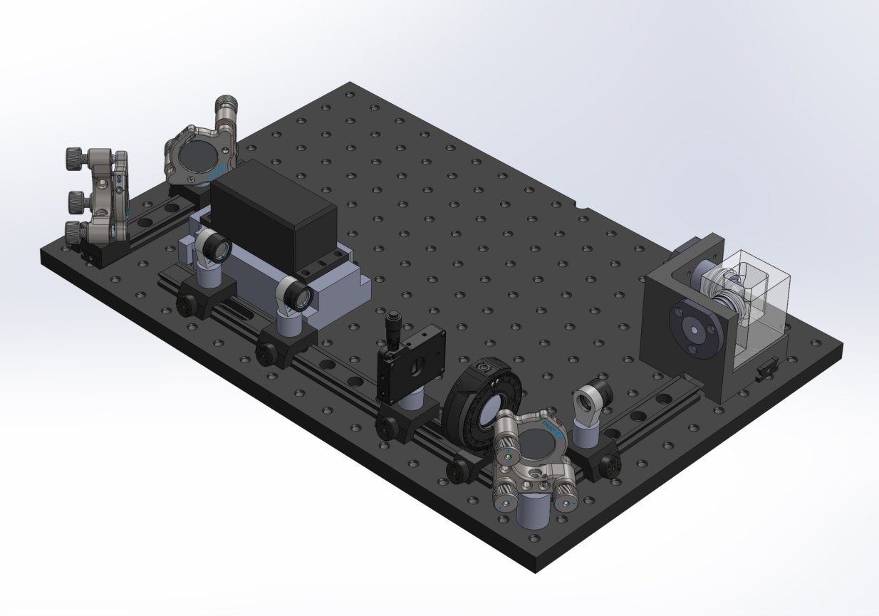


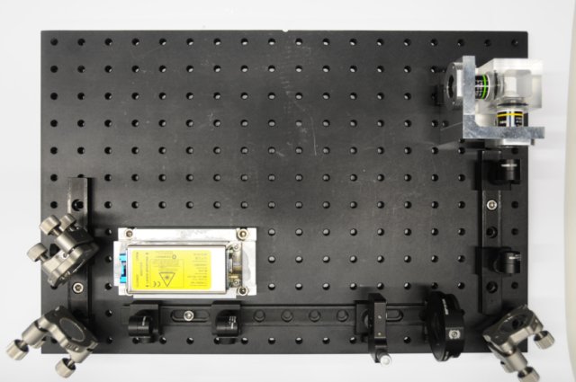
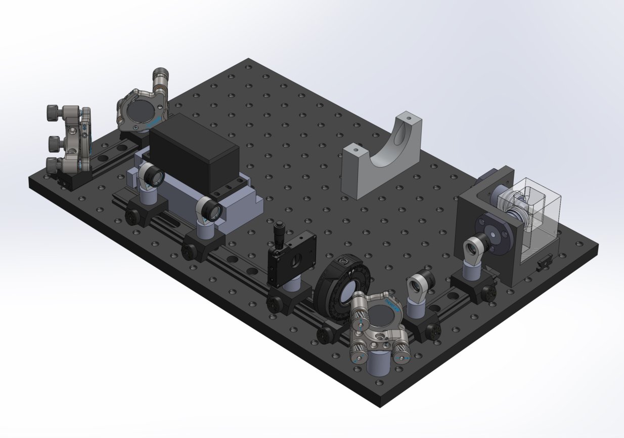
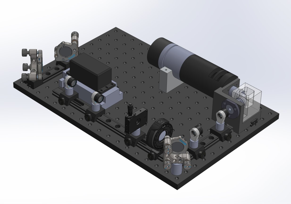
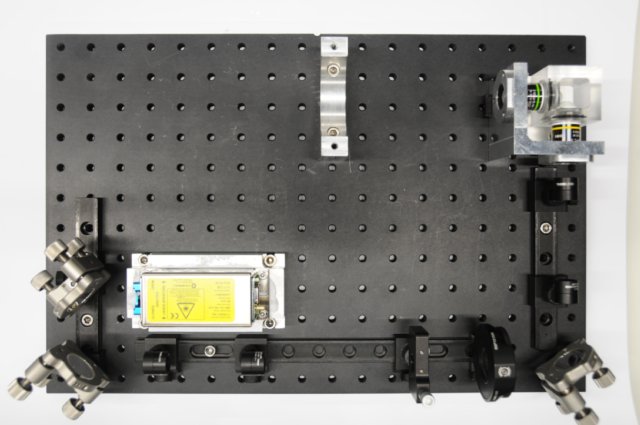
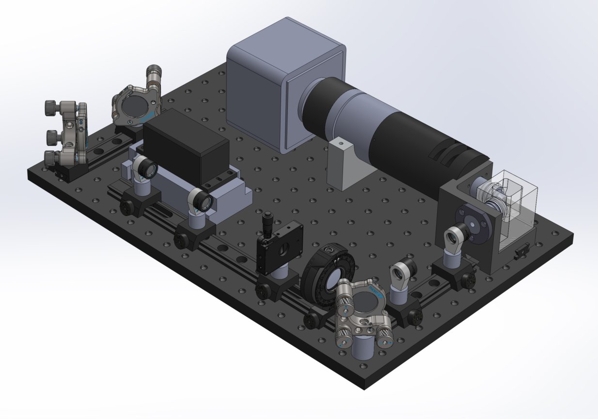
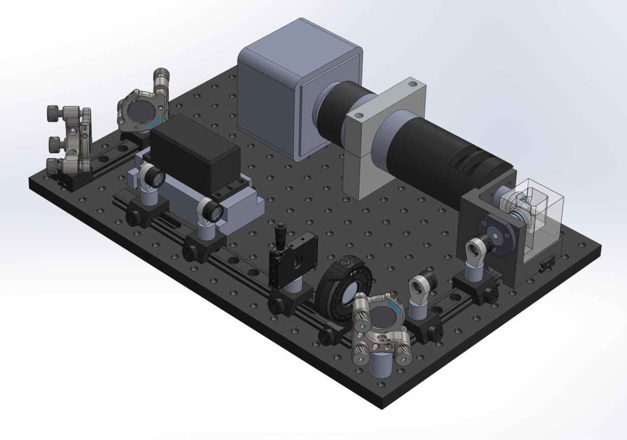

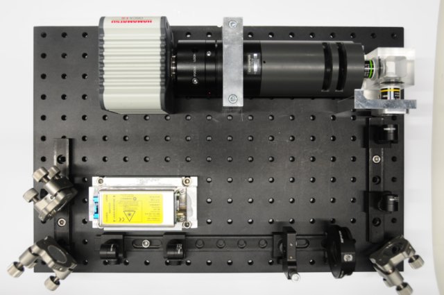
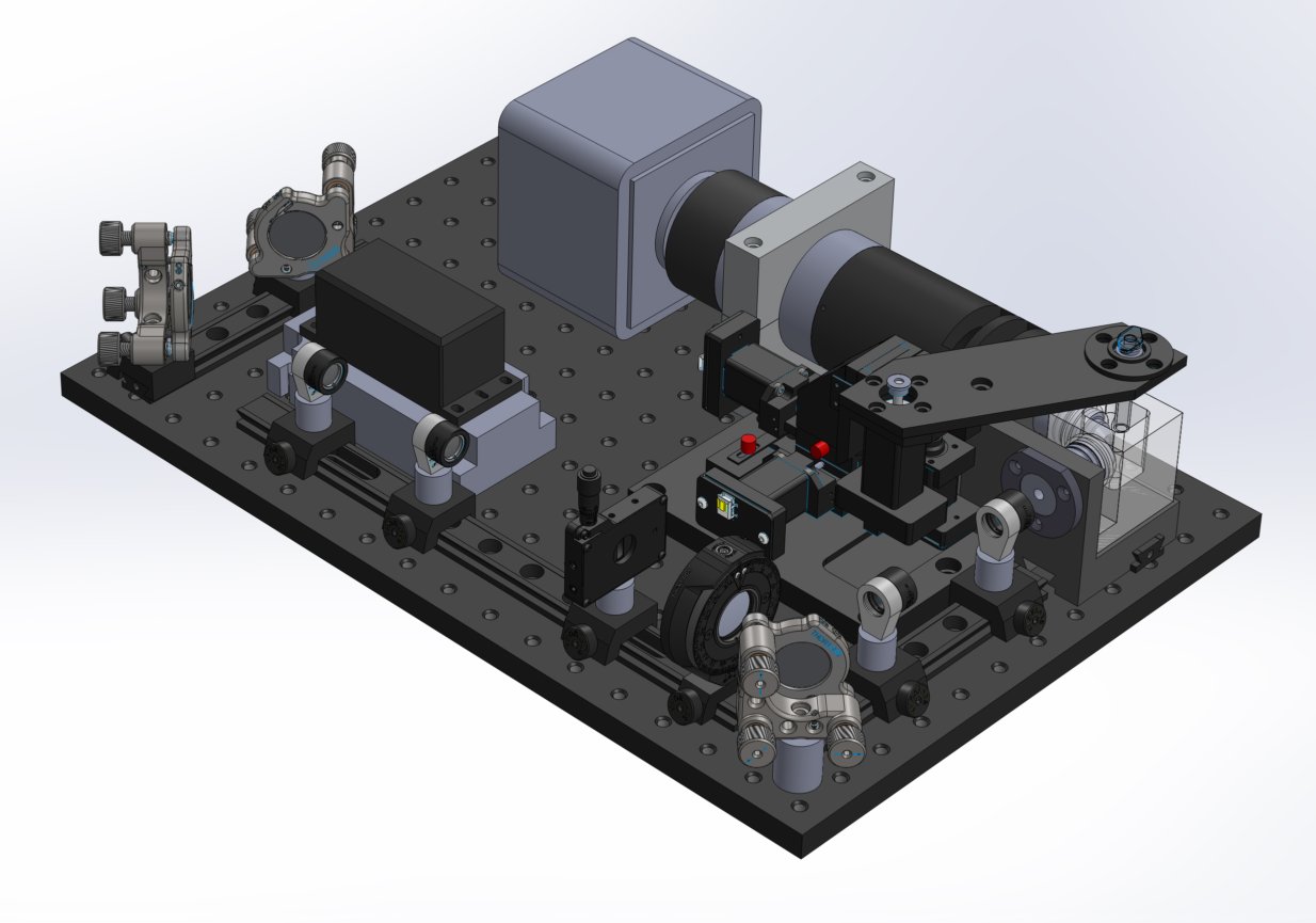
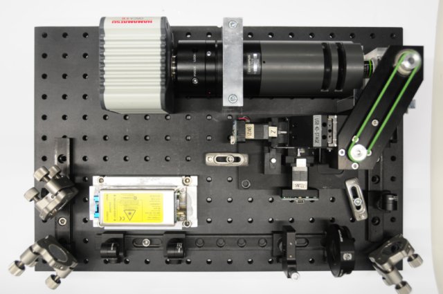
Now connect the system to the computer and you are ready for operation.