Installing the 4D motor system
Objects needed
- 1x Assembled USB-4D-Stage motor system
- 2x Variable Height Clamp (either CL3/M 2" or CL2/M 3")
- 4x M6 threaded capscrews (2x M6 x 25 mm and 2x M6 x 20 mm)
Tools needed
- 1x 5 mm hex key/driver
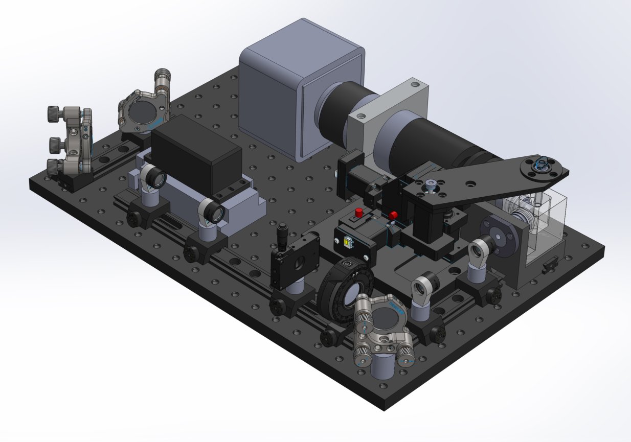
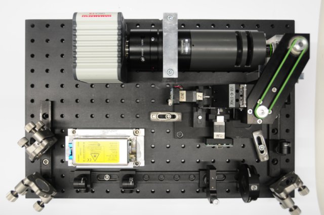
How to attach and position the motor system on the breadboard
Place the assembled 4D motor system into the empty middle section of the optical breadboard with the Z-motor axis parallel with the detection axis. The sample arm should be in such a position that the ball bearing hole is over top from the sample chamber. Making sure that the motors are in their fully retracted positions, place the center of the sample arm's ball bearing hole directly over a position that is about 1.5-2.0 mm in front of the glass surface of both lenses. This is 2.0-1.5 mm behind the focal plane of either lens both of which have a 3.5 mm working distance.
Take both M6 x 20 mm capscrews, screw them in to the variable height clamps threading on the end until the height of the clamp is the same as the base of the motor. Then using both the M6 x 25 mm capscrews, find a good position that will be clear of any moving parts, and screw the clamps down to the breadboard.
Installation of 4D motors
|
|