From OpenSPIM
3. Fine alignment of the light-sheet for the sample using beads
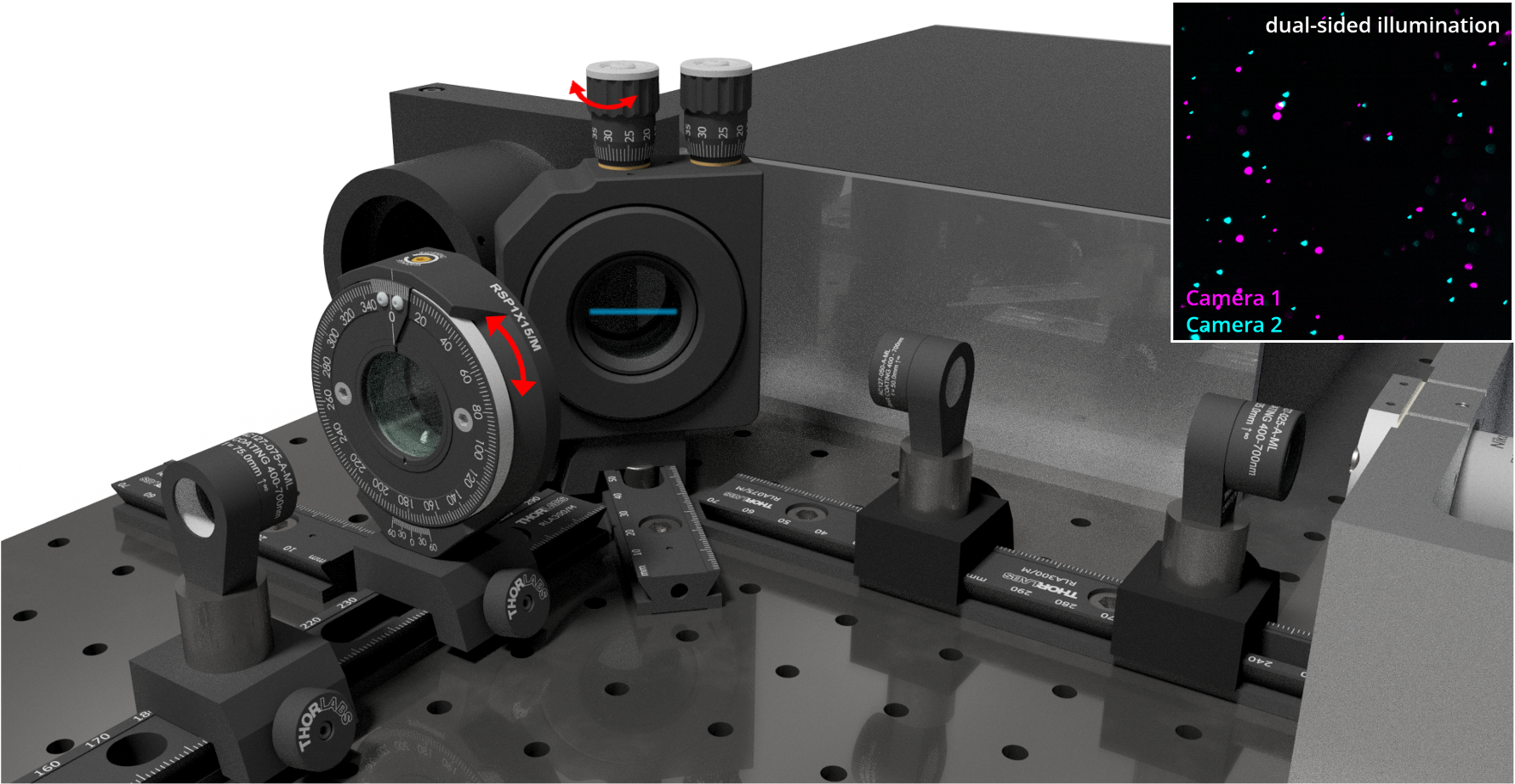
Step 13 Place the cylindrical lenses on the rail and put back the emission filter. Make sure the cylindrical lens is in its correct place and its rotational mount is well adjusted by checking whether a focused, horizontal laser stripe has appeared on the corner mirror surface.
Step 14 Test the alignment of both excitation light-sheets on fluorescent beads. For this, use the horizontal gimbal mount knob to bring the light-sheet into the focal plane of one of the detection objectives, while simultaneously gently playing with the rotation mount of the cylindrical lens (see Figure 11, red double-headed arrows). The beads embedded in agarose should become focused and visible and ideally cover the field of view homogeneously as small bright dots as shown in the inset of Figure 11.
Click here in case different light intensities between both illumination sides are observed
Different light intensities of the beads between the left and right illumination axes may indicate slight beam alignment differences. This issue can be corrected by looking at the beads. In the illumination axis, where a lower intensity of beads is observed, the height of the beam can carefully be adjusted by using the two reflecting mirrors positioned prior to the rail carrying the first telescopic system. By making slight adjustments with a 5/64" hex key adjuster, intensities should increase and decrease. Aim to maximize light intensity on both illumination axes.
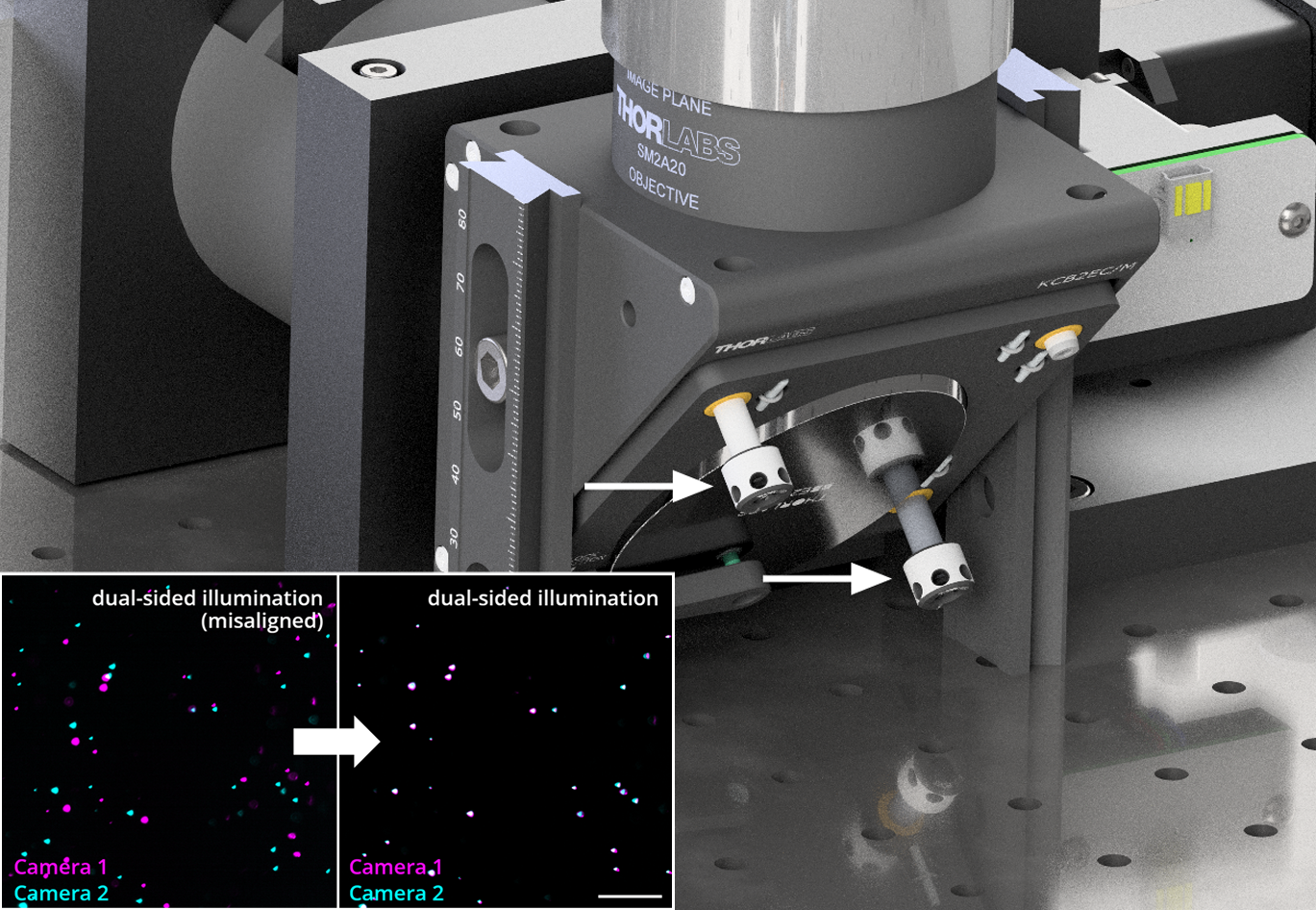
Step 15 Overlap of both field of views (camera one and two) by using the fine adjustments of the corner mirror mount knobs (see Figure 12, white arows) while looking at the beads.
Click here for more details on Step 15
Make sure the same beads are visible in the two sister cameras and that the beads are co-focused by moving one of the detection objectives in z. Then use the corner mirror mount knobs (Figure 12, white arrows) of the 2-inch corner mirror mount (KCB2EC/M, Thorlabs) to co-align the two field of views until all beads overlap. If a significant stronger mismatch of beads is visible at the outer corners of the field of view and the impression of a spiraling feeling occurs while going through the beads in z, then one of the two cameras has to be rotated before the overall match of the beads can be improved (see also Step 12).
Congratulations, your OpenSPIM is now aligned!