From OpenSPIM
1. Aligning the laser beam along the rails
Click for details on mirrors and alignment disks used in the depicted X-OpenSPIM system
For the alignment along the rails, which carry the optical components of the first and second telescope system, one can use Ø1/2" mirrors (BB05-E02, Thorlabs) mounted on kinematic mounts (KM05/M, Thorlabs) and larger Ø1" corner mirrors (BB1-E02, Thorlabs) mounted on gimbal mirror mounts (GM100/M, Thorlabs). Note that the corner mirror is a modification of the original OpenSPIM design and is placed on its own short rail piece that was cut off from a 300 mm optical rail (RLA300/M, Thorlabs).
All mirrors placed into a kinematic mount should be adjusted to approximately 45 degrees to ensure a perpendicular bounce of the beam.
After the alignment, the emitted laser beam will hit roughly the center of all mirrors and ends at the center of the illumination objective. To achieve this, two separate reference points are needed at the correct height. In a typical OpenSPIM setup, the beam would be elevated 50 mm off the surface of the breadboard. For the reference points, one can use e.g., nearly closed iris apertures (SM1D12D, Thorlabs), alignment disks (DG05-1500-H1-MD, Thorlabs) or alignment disks created via alignment plates (LMR1AP) for lens mounts (LMR1/M). We used the latter placed on 1" rail carriers (RC1, Thorlabs) to create both reference points at the correct height. In the following, the two reference points will be called AD1 and AD2 respectively.
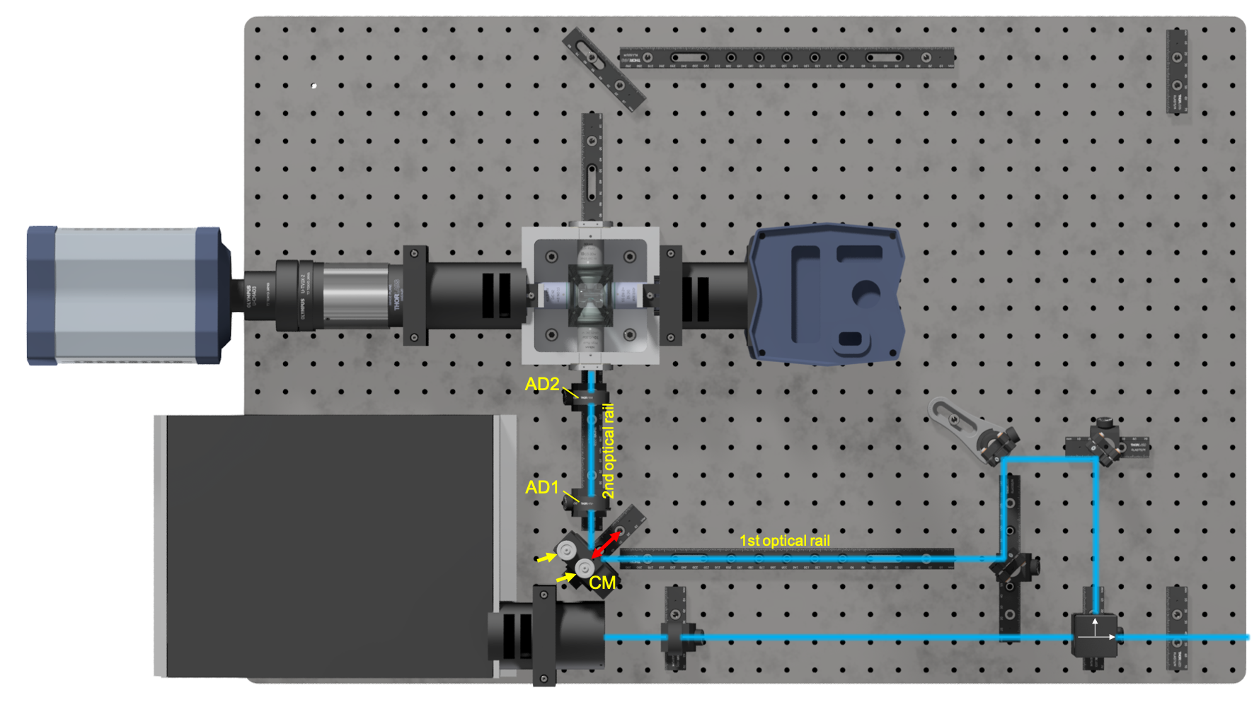
Step 1 Remove any optical parts from the illumination axis except for the kinematic mirrors (KM) and the beam splitter cube (see Figure 1). If available, place a density filter (e.g., OD: 2.0) close to the exit face of the laser housing and set laser intensity to a minimum. The beam should be barely visible to the eye for safety reasons.
Step 2 Adjust the beam splitter cube and aim for two beams that are perpendicular to each other when they hit the first two kinematic mirrors. Careful! The perpendicular beam path branching off the beam splitter easily tilts to one side, but this should be avoided (see yellow dotted line in Figure 1).
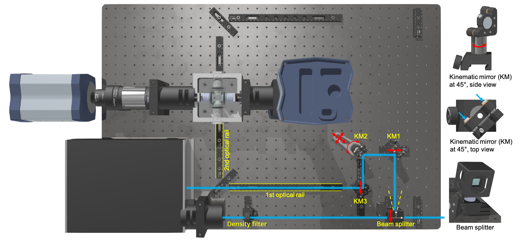
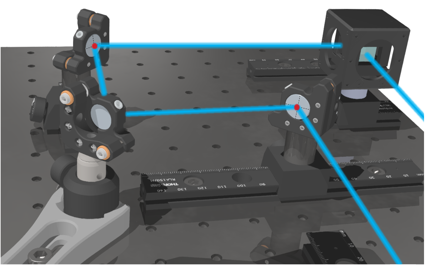
Step 3 Adjust all kinematic mirror mounts to 45 degrees until the laser beam roughly follows the path along the optical rails (see Figure 1). Try to find the central spot of each KM as indicated in Figure 2.
Click here for more details on Step 3
This step requires some patience, because in order to achieve a perpendicular bounce, kinematic mirrors have to be taken off the breadboard, then readjusted (slightly turned as shown in Figure 1, side view of KM) by loosening and tightening their rail carriers, and then placed back on the optical breadboard and into the beam path. This typically requires several attempts. Ensure that the laser hits approximately the center of each mirror and try to minimize using the fine adjustment screws as they need to have sufficient margin (Step 4) and should retain a more or less neutral position.
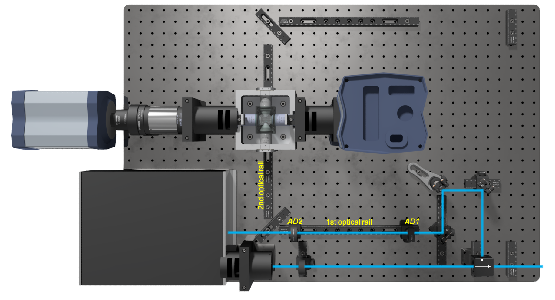
Step 4 Place the first alignment disc (AD) at the beginning of the first optical rail and the second alignment disc at its end, as depicted in Figure 3. Readjust the kinematic mounts (KM05/M, Thorlabs) of the reflecting mirrors until the beam hits both central holes of the two reference points (AD1 and AD2) and the central spot of all kinematic mirrors.
Click here for more details on Step 4
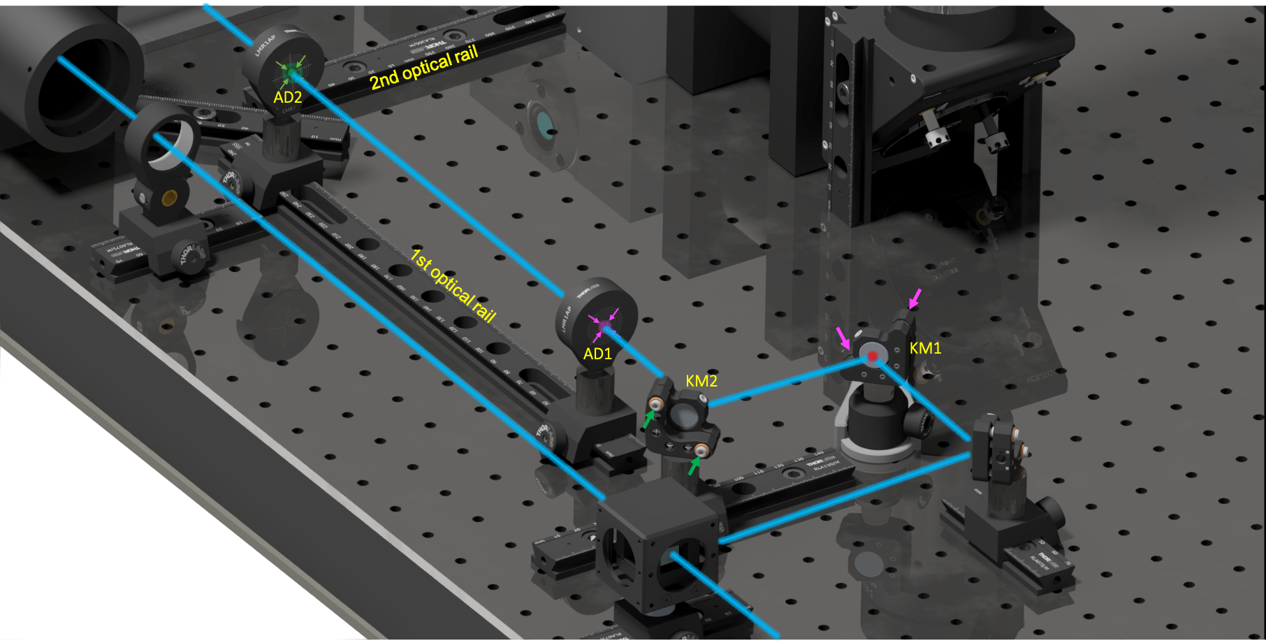
Start with the first kinematic mirror (KM1) using the fine adjustment screws (pink arrows, Figure 4) and aim for the central opening of the first alignment disc (AD1). Then adjust the second kinematic mirror (KM2, green arrows) but, this time, try to hit the central hole of the second alignment disc (AD2). The laser beam will not hit the alignment disc right away. Instead, it typically diminishes before reaching the central hole of the alignment disc. Whenever this is the case, go back to the first kinematic mirror (KM1) and readjust for the Iris aperture hole. Play this back and forward until the beam strikes both reference points and the first optical rail is correctly aligned.
Step 5 Proceed aligning the second optical rail between the corner mirror and the illumination objective of the chamber. Again, place the two reference points at the beginning and the end of the rail and move the Gimbal mount of the corner mirror (see Figure 5).
Click here for more details on Step 5
Initially the Gimbal mount knobs of the corner mirror should be brought into a neutral position and the first alignment done by sliding the corner mirror forward or backward along the rail (Figure 5, red double headed arrow). There should be a reasonable alignment of the beam before tightly fixing the mirror onto the rail. The beam can be aligned by adjusting the corner mirror with the horizontal (H) and vertical (V) adjuster knobs of the Gimbal mounts until the beam passes directly through the center of both alignment disc holes.
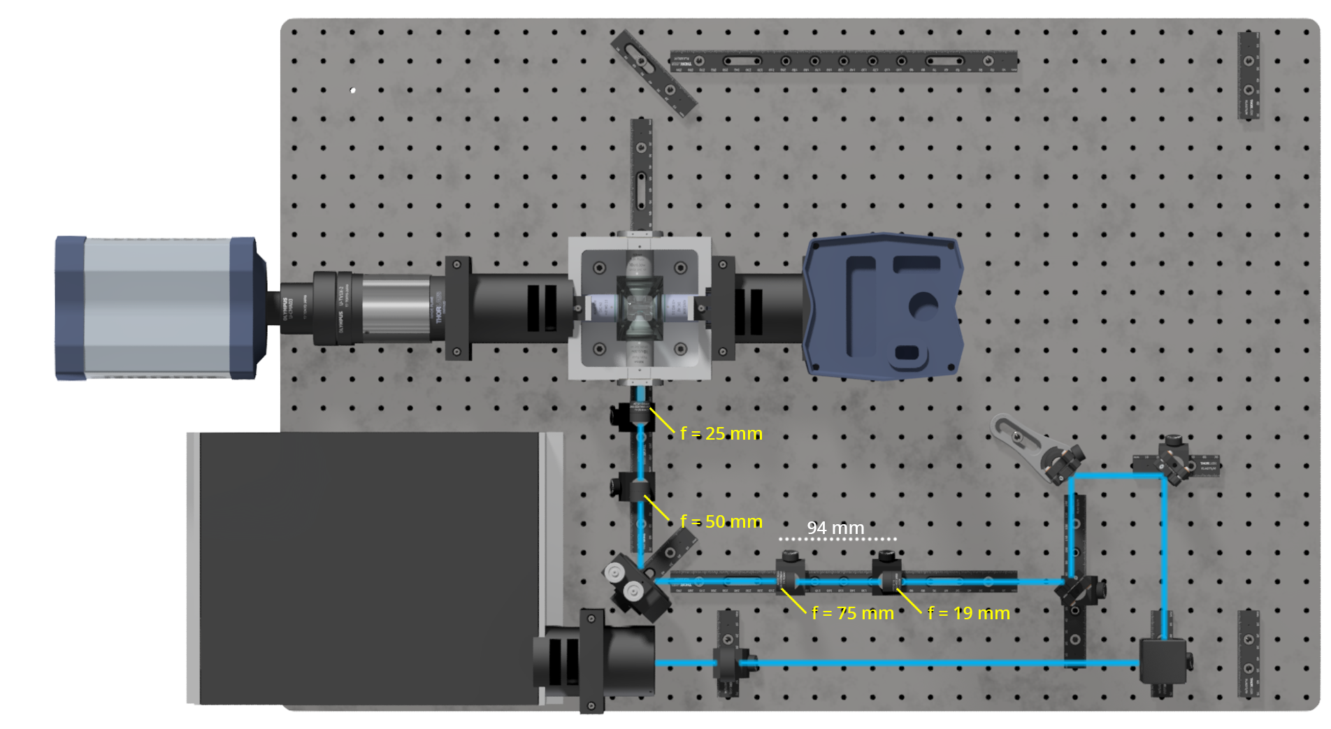
Step 6 Mount the lenses of the first telescope system as shown in Figure 6 (without the cylindrical lens) and make sure that the distance between them roughly equals the sum of their focal length (e.g., 19 mm and 75 mm means that the distance between the two lenses should be 94 mm as depicted in Figure 6).
Click here for more details on Step 6
Note that by placing the first two telescopic lenses (19 mm and 75 mm), the beam significantly expands. Follow the enlarged beam starting behind the 75 mm telescopic lens (a piece of lens cleaning tissue will do) and check if the beam retains the same diameter along the rails until it hits the corner mirror. At this point, it may be a good idea to verify whether the insertion of the telescopic lenses did not severely alter the alignment of the laser beam. This can be checked by placing an alignment disk at the end of the rail. Such misalignment are common and can be avoided by ensuring that the telescopic lenses are tightly assembled and that the lens mounts face the illumination axis without any tilt. One might need to make minor adjustments using the screws of the kinematic mounts to correct for small deviations of the beam caused by the inserted lenses.
Step 7 Repeat step 1-6 to align a second illumination axis.
Continue to part 2 of the alignment guide