From OpenSPIM
2. Visualizing and tuning the beam within the field of view of one or two cameras
After the alignment along the rails carrying the optical components is completed, the emitted laser beam can be visualized in agarose and adjusted by slightly changing the positions of the spherical lens assemblies along the rails.
Preparations:
- Prepare 1% agarose with fluorescent beads
- Fill the acquisition chamber with water
- Mount the glass capillary and find the agarose within the field of view using a bright light source
Click here for more details:
-
Prepare 1% water agarose containing fluorescent beads (e.g., 1:2000), which fit the laser excitation and emission filters of your OpenSPIM system. Sonicate the beads in a 1:100 stock solution for 3 min before mixing them with water agarose or vigorously vortex it for several minutes to avoid clustering.
-
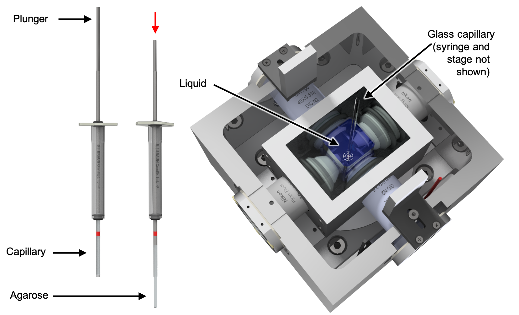
Vortex the Agarose containing the beads for 3 min and soak it into a glass capillary e.g., by using a plunger. In case of an X-OpenSPIM we recommend to already mount some kind of sample, which can be easily spotted. For detailed descriptions for mounting and preparing samples visit the OpenSPIM website.
-
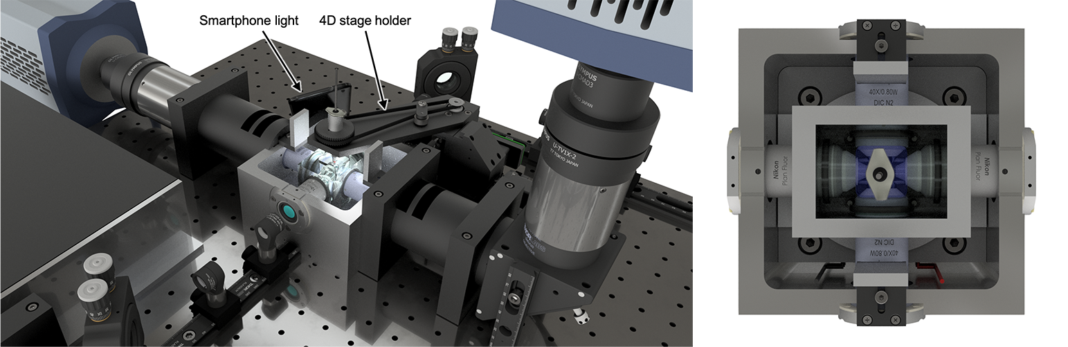
Fill the acquisition chamber with water, mount and find the lower edge of the glass capillary using any available bright light source (even the torch of your phone can be used). Then push out the agarose by gently pressing the plunger until the column of agarose can easily cover the entire field of view. Make sure the glass capillary is completely out of view and only agarose is visible.
-
Use the 4D-stage to focus on the left or right edge of the agarose and center the column of agarose in the field of view. A smartphone's bright light source is sufficient find the capillary and bring it into the field of view.
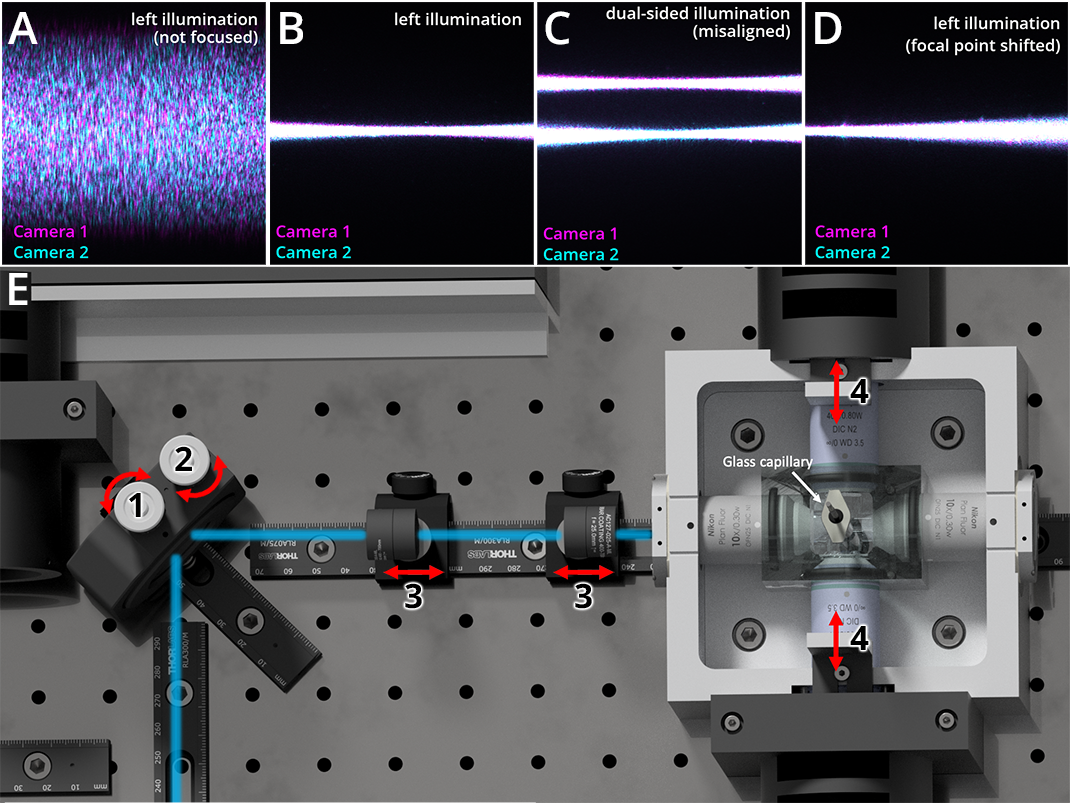
Step 8 Remove emission filters and cylindrical lenses on the illumination axes used for alignment and slightly adjust the distance between the 25 mm and 50 mm telescopic lenses and their distance to the illumination objective (Number 3 in Figure 9, E) to find and visualize the beam.
Click here for more details on step 8
Try tightening the two telescopic lenses with the spring-loaded plunger of the rail carrier, up to the point where they can barely glide along the optical rail (Figure 9, red double headed arrows). At some point, the laser beam will become visible, first as an indistinct broad fuzzy beam crossing the field of view horizontally from left to right. Further adjust the telescope lenses to increase the sharpness of the beam until it looks similar to the one depicted in Figure 9, A.
Step 9 Adjust the horizontal gimbal mount knob of the corner mirror to bring the illumination beam in focus with the working distance of the detection objective (Number 1 in Figure 9, E)
Click here for more details in step 9
The beam should now be seen as a very thin stripe instead of a coarse beam (see Figure 9, B). At this point, it often becomes obvious that the focal point of the beam is not centered in the field of view. This shift is shown in Figure 9, C. Again, carefully adjust one of the telescopic lenses (Number 3 in Figure 9) by gently gliding it along the optical rail to correct for this shift (red double headed arrows).
Step 10 Repeat step 4 to 6 on the second illumination axis until the left and right illumination beams are aligned and resemble the aligned beam depicted in Figure 9, B.
Click here in case a second camera is used
Once both illumination sides are aligned and a beam is clearly visible within the FOV of one camera (using no cylindrical lenses and no emission filters), then the detection objective of the second camera should be adjusted up to the point where the beams of both detection axes are highly similar in shape and clearly visible as demonstrated in Figure 9, C.
Careful! Particularly in an X-OpenSPIM setup with two detection objectives, it is crucial that the glass capillary with its column of agarose is positioned well in the center of the chamber before proceeding with this alignment step!
Initially, any bright field light (e.g. phone flashlight) can be used to find any given structure (e.g., the bottom left or right edge of the capillary or some kind of recognizable spot/sample). Gently slide the detection objective of the second camera forward and backward along the detection axis until the same structure becomes visible. Also the corner mirror mount knobs (KCB2EC/M, Thorlabs) installed in on of the detection axes have to be adjusted to bring the two fields of views closer together until they can fully overlap. This alignment should subsequently be repeated using pure agarose in which the beam of one illumination serves as the new alignment target (see also Figure 12). Ensure that both sister cameras have the same top and bottom orientation.
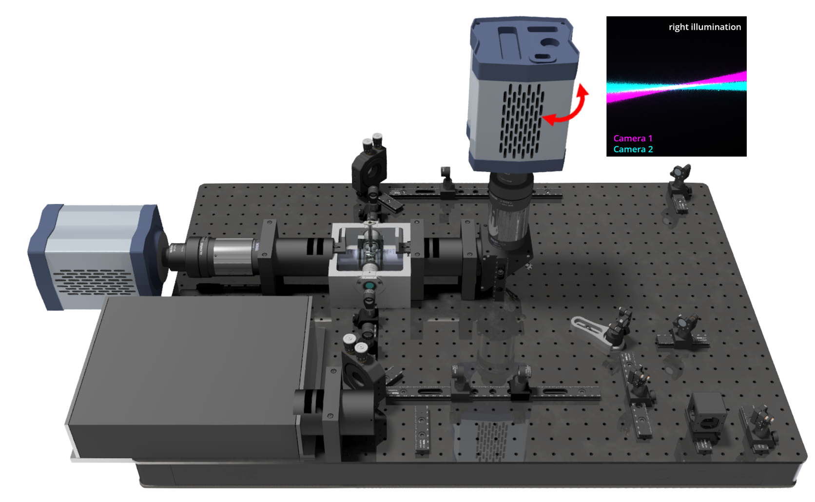
Step 11 Adjust the vertical gimbal mount adjuster knob to center the beam (Number 2 in Figure 9, E). In this way, both illumination paths are aligned and centered in the field of view until they overlap each other.
Step 12 Check if any rotational misalignment between the field of view of both sister cameras is visible. An example of this can be seen in Figure 10 (inset). If this is the case, one camera has to be rotated (Figure 10, red double-arrow) until the mismatch is corrected.
Continue to part 3 of the alignment guide