From OpenSPIM
![]()
Quick Navigation
=> Go to Detailed Acquisition controls for µOpenSPIM. <= Return to the µOpenSPIM starting page
Getting familiar with µOpenSPIM's GUI
- The GUI of µOpenSPIM can be arranged in many ways and then saved and restored if needed. Click here for more information and help.
Acquisition Controls
The following image will introduce you to the location of the available controls to set up an imaging session. For more detailed descriptions of the acquisition controls follow this link: Detailed Acquisition controls for µOpenSPIM.
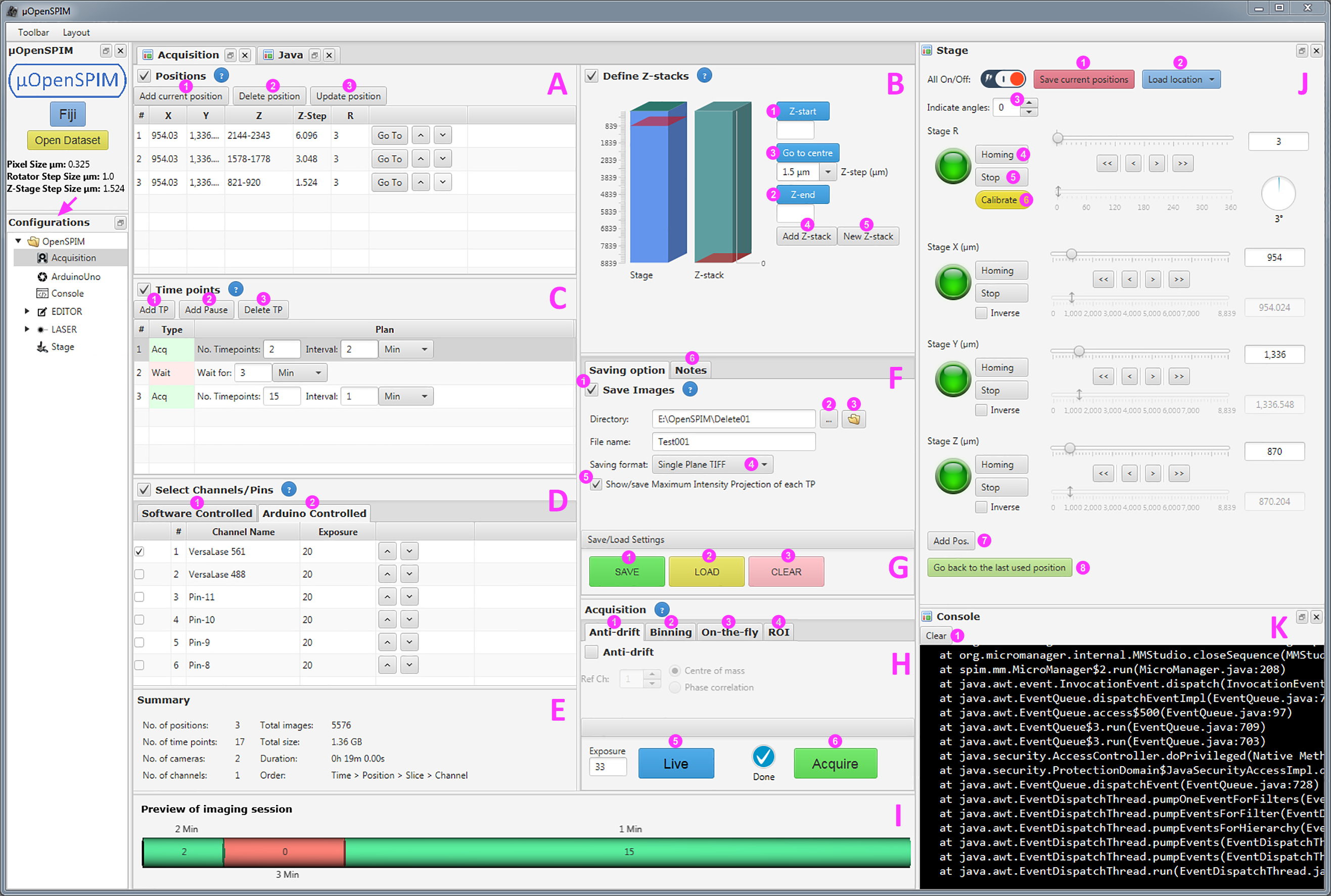
(A) Positions (B) Define Z-stacks (C) Time points (D) Channels (E) Summary (F) Saving options (G) Save/Load settings (H) Acquisition (I) Preview of imaging session (J) Stage (K) Console
Acquisition with µOpenSPIM
The process of acquiring images ranges from snapping a single image to recording overnight (or longer) time lapses of samples from N different angles.
Acquiring a Single Image
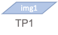 To acquire a single image with µOpenSPIM:
- Navigate the 4D stage (J) to the location you want to image.
- Click Add current position to add this plane to the position list.
- Click Add TP and set both, the number of time points (TP) and the interval, to 1.
- Add at least one channel to the Software Controlled Channels list or select one of the Channels that are available in the Arduino Controlled Channels list. Don't forget to set the desired exposure time of each channel.
- You may specify an Output directory
 if you would prefer the image be written straight to disk, rather than opened in µManager using the computer memory. A metadata.txt file of all acquisition settings will also be saved into the Output directory.
 - Finally, click Acquire to capture a single or multi-channel image.
Acquiring a Stack
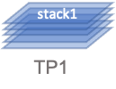 A stack is a sandwich of many image slices of different focus levels of the sample with a defined beginning and end. To set up a stack requires to move the Z stage.
- Navigate to the sample location where the Z stack should begin.
- Click Z-start and the current Z position will now show up next to the button.
- Navigate to the sample location where the stack should end.
- Click Z-end and the current Z position swill show up once again next to the button.
- Click Go to centre and check if the Z Stage ends up in the middle of the stack. This is a good way to know that the Z stack has been set correctly.
- Specify the Z-Step Size (in μm).
- Click Add Pos. to add the newly defined Z stack to the position list on the left. It will also include the X, Y, and R positions.
- Click Add TP and set both, the number of time points (TP) and the interval, to 1.
- Add at least one channel (either Software Controlled or Arduino Controlled) to the Channels list and set each channel's exposure time.
- Though a single stack can easily fit into the memory, it is recommended that you specify an Output directory so the stack is saved to the disk. A metadata file of all acquisition settings will additionally be saved into the Output directory.
- Optionally:
- turn on Show/Save Maximum Intensity Projections of each TP to receive a Maximum Intensity Projection (MIP) after the stack has been fully acquired. The MIP will be saved into its own sub-folder within the Output directory.
- Click Acquire to capture the defined stack.
Single-Plane Time Lapse
 To acquire a time lapse of a single plane, set up the recording exactly as if you were going to record only one image.
-
After clicking Add TP specify how often the plane should be imaged and set its recurring time interval (in seconds, minutes, hours or days).
- Optionally you can add acquisition breaks by clicking Add Pause. Then specify the length of the acquisition break and click Add TP to continue with a new time lapse recording after the acquisition break.
-
Add at least one channel (either Software Controlled or Arduino Controlled) to the Channels list and set each channel's exposure time.
-
Clicking this button will allow you to specify an Output directory. A metadata file of all acquisition settings will additionally be saved into the Output directory.
-
Optionally:
- Enable Anti-Drift: choose between Phase Correlation (functionality is based on the 3d-stack with x, y, and z coordinates) or Centre of Mass (functionality is only based on x, y coordinates). Note that beads surrounding the sample might affect the Anti-Drift.
- Enable Binning: Choose one of the binning options and press apply.
- Enable On-the-fly: This will enable the “process()” method of a running script, which can be created or edited within the Java Editor (Editor > Java). You can give it a try by running the "ClijxMaxFusionDoG" example script located within the Java Editor. Press "Run" to execute it and make sure the "On-the-fly" box in the Acqusiiton panel is ticked. The example script will fuse (maximumImages), substract background of the fused stack (differenceOfGaussian3D) and create a MIP (maximumZProjection). The three operations take place on the graphics processing unit (GPU) using the GPU-accelerated image processing library (CLIJ2) and the three output files will be saved into the specified output directory into a subfolder called "output". Make sure you specify the correct number of channels inside the script before you start aciring images.
- Select a region of interest (ROI): Select a ROI with the Rectangle tool in the µManager's preview window, which will pop up when you click Live View. Then click Apply.
-
Click Acquire to begin the time-lapse recording.
Single-View Time Lapse
 To record a single view/stack of a sample over time:
- Navigate the 4D-stage to the location you wish to acquire images and specify the beginning and the end of the Z stack and the Z-Step Size (in μm) as described above. In the Picard 4D-stage the minimum Z step size is 1.524 µm.
- Click Add Pos. to add the newly defined Z stack to the position list on the left and specify how often the stack should be imaged and set the recurring time interval (in seconds, minutes, hours or days).
- Clicking this button will allow you to specify an Output directory. A metadata file of all acquisition settings will additionally be saved into the Output directory.
- Optionally:
- Enable Anti-Drift: choose between Phase Correlation (functionality is based on the 3d-stack with x, y, and z) or Centre of Mass (functionality based on x, y). Note that beads surrounding the sample might affect the Anti-Drift.
- Select a Region of interest (ROI): Select a ROI with the Rectangle tool in the µManager's preview window, which will pop up when you click Live View. Then click Apply.
- Enable Binning: Choose one of the binning options and press apply.
- Turn on Show/Save Maximum Intensity Projections of each TP to receive a Maximum Intensity Projection (MIP) after the stack has been fully acquired. The MIP will be saved into its own subfolder within the Output directory.
- Click Acquire to begin the multi-view time-lapse recording.
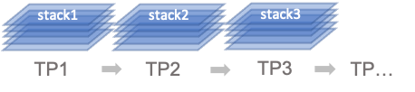
Multi-View Time Lapse
 To record multiple views of a sample over time:
- For each view:
- Navigate the 4D-stage to the location you wish to acquire images.
- Specify the beginning and the end of the Z stack and the Z-Step Size (in μm) as described above. In the Picard 4D-stage the minimum Z step size is 1.524 µm.
- Click Add Pos. to add the newly defined Z stack to the position list on the left.
- After clicking Add Pos. specify how often the stack(s) or view(s) should be imaged and set the recurring time interval (in seconds, minutes, hours or days). Add acquisition breaks by clicking Add Pause and specify its length. Click Add TP to add new time lapse span which will continue after the acquisition break.
- Clicking this button will allow you to specify an Output directory. A metadata file of all acquisition settings will additionally be saved into the Output directory.
- Optionally:
- Enable Anti-Drift: choose between Phase Correlation (functionality is based on the 3d-stack with x, y, and z) or Centre of Mass (functionality based on x, y). Note that beads surrounding the sample might affect the Anti-Drift.
- Select a Region of interest (ROI): Select a ROI with the Rectangle tool in the µManager's preview window, which will pop up when you click Live View. Then click Apply.
- Enable Binning: Choose one of the binning options and press apply.
- Turn on Show/Save Maximum Intensity Projections of each TP to receive a Maximum Intensity Projection (MIP) after the stack has been fully acquired. The MIP will be saved into its own subfolder within the Output directory.
- Click Acquire to begin the multi-view time-lapse recording.