EMBO 2014 Team SiedyZsig
Projects
Fusion of 12 registered views
Deconvolution of 12 registered views
Studying MCF-10A morphogenesis in 3D cell culture
Imaging a fixed, large spheroid (ø ≈ 500 µm) on Zeiss Lightsheet Z.1
- Sample preparation
We used a cell line expressing GFP-tagged histone 2B. The spheroid was embedded together with beads in 1 % agarose in a glass capillary (black label).
-
Imaging
- 1 timepoint, 6 angles, dual-side illumination
- excitation: 488 nm
- detection: 20x ...
-
Results
After approximately 2 h 6 min (2 h to set up the acquisition, 6 min to run it) we had a nice 36 GB data set.
Fortunately we decided not to fuse the two illuminations online during acquisition, but to keep them separate: We compared a simple fusion of the two unregistered illuminations for one angle to the result after performing a nuclei-based registration. Indeed the two views were shifted in z (detection direction) by ≈ 10 µm—a nice example for large samples causing aberrations.
Finally we registered all 12 views with nuclei and fused them. An additional deconvolution using beads to determine the PSF produced an even crisper image. However, we had to crop the image (and consequently cut part of the spheroid) in order to limit the required memory to the 108 GB RAM available.
Overnight time-lapse imaging of living, 4-days-old spheroids (ø ≈ 50 µm) on Zeiss Lightsheet Z.1
- Sample preparation
H2B-GFP cells were additionally labelled with the live-dye SiR-tubulin (Lukinavičius et al. 2014). They were embedded as single cells in Matrigel and injected into chambers made of either 1 % Gelrite or 1.5 % agarose. We incubated the chambers and let the cells proliferate and form small spheroids for four days.
In a second attempt we seeded single cells in Matrigel into FEP tubes, but they died of oxygen deficiency very quickly.
- Imaging
Unfortunately the Gelrite/agarose chambers were too thick compared to the working distance of the imaging objective. Thus we could not take any images of living spheroids.
Imaging of the two-photon laser-induced brain ablation in the zebrafish larvae
introduction and overview
I am interested in tissue regeneration in the zebrafish, especially brain regeneration after traumatic injury. In my PhD, I focus on immune cells that are main players in the inflammation because we characterized acute inflammation as a positive regulator of the brain regeneration. Considering dynamic property of those cells and days-long process of inflammation, obtaining spatio-temporal information microscopy in which specimen gets minimum photo-toxicity and photo-bleaching is an attracting topic of research. Therefore, we decided to study dynamics of immune cells by SPIM.
In this course I would like to observe neuron dynamics in the zebrafish brain after traumatic injury induced by two-photon laser. I visited Gene Myers lab as they have excellent equipment on their SPIM, two-photon light sheet laser which is used to make injury and single-photon light sheet microscope which allows immediate observation. In addition, I used an Open-SPIM only for observation after the ablation with Myers' SPIM because it has more similar equipment to ours which we are going to assemble in a month.
Laser-induced ablation and SPIM observation @ Myers' lab

Scheme for sample orientation
-
Sample Preparation and Laser Ablation
- 2 days post fertilization
- PTU treated: to inhibit pigmentation
- Expressing Ras-GFP: labeling cellular membrane
- Special thanks to Jaroslav (Norden Lab), Michael and Michaela (Huiskin Lab)
- The zebrafish are anesthetized with tricane (200µg/mL) and embedded into FEP tubes (inner and outer diameters: 0.8mm and 1.6mm, respectively)filled with 0.1% agarose containing tricane.
- A tube was fixed to a metal-based sample holder with adhesive tape as shown in the picture on right.
- To make the nearest access of the laser to the brain, the tube was rotated dorsal-side upright (see the scheme).
- By confining area of light sheet illumination with high-power two-photon laser, we succeeded to make well-targeted injury as shown on the right.
- Parameters for laser ablation
Laser ablation of the zebrafish brain expressing a fluorescent membrane marker
- Laser power: <600mW
- Wave length: 920 nm
- Duration: <2 sec
There are two different types of light sheet; conventional static light sheet created by cylindrical lens and scanning light sheet. The Myers' SPIM has the latter one. Illumination without scanning gives size limitation of the LS in Y direction.
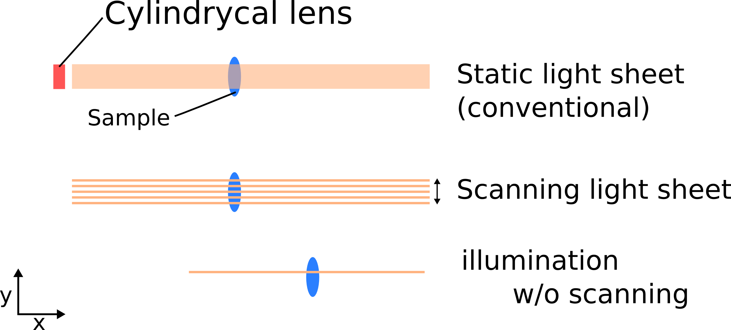
By changing N.A. of excitation lens changing thickness of light sheet is available. A thinner light sheet was applied to make a well-confined laser area. Refer to this paper from Betzig's group: Gao et al., Nature Protocols 9, 1083–1101 (2014)
-
Imaging and result
- Objective lens: 40x 0.8 N.A. Water dipping, NIKON
- Area: 331x331µm sq, 1µm x 100 Z stacks/time point, Single angle
- Excitation: 488nm, <2mW, exposure for 16 msec in average, single side illumination
- Time-lapse: Every 30min for 12hr
- Special thanks to Nicola (Myers Lab)
The movie shows the brain shrank soon after the ablation and tissue components running out of the injured tissue were captured. After shrinkage the brain bunched up due to either development or tissue elasticity of the brain as it's often referred as sponge-like structure. Observation of the other brain hemisphere with lower magnification will define the cause of this morphological
SPIM observation with Open-SPIM
Development of the central nervous system in zebrafish larvae

Color spectrum of the movie, showing depth of the each fluorescent beads. 1 frame=1µm
-
Sample Preparation
- 3 days post fertilization
- PTU treated: to inhibit pigmentation
- Expressing HuC-GFP: labeling neuron
- Sample has already been ablated with Myers' SPIM
-
Imaging and Result
Objective lens: 20x 0.5 N.A. Water dipping, Olympus
- Area: 26 x 22mm sq, µm x 134 Z stacks/time point, Single angle
- Excitation: 488nm, <2mW, single side illumination
- Time-lapse: Every 10min for 18.5hr
- Special thanks to Pete (Tomancak Lab)
Unfortunately we could not find an injured spot with this sample. When we were trying to make an injury, we could not define ROI well because, somehow, this transgenic line emitted very blur fluorescence. It might be because of the highly-compacted population of the neurons in the brain. In this time-lapse movie, neurons are coloured according to the depth of them within the sample. The movie shows dynamics of neurons over developmental stages at single-cell level. During imaging the fish moved and the focusing Z positions were shifted. This movement is most likely due to the development not voluntary movement. This is inevitable when working with zebrafish larvae, therefore, It would be solved by better manipulation of data processing or development of a new function of 4D-SPIM stage coupled with the camera, for instance, auto-chasing of a certain remarkable structure in the specimen.
Data Processing Procedure
Since we could not register the images from Open-SPIM in a way the majority of the people does, probably because of high level of neuron compaction in the brain, we took another way of processing. This might be a unique case, thus, I would like to report here what steps we followed. Special thanks to Olivier
-
Concatenation of the images
- Open all the tif images that you would like to make into time-lapse.
- Image>Stacks>Tools>Concatenate>All Open Windows
- The resulting file contains the Z-stacks and the time points, however, it does not have two channels that are for Z-stack and time lapse.
-
Hyperstacking into a 4D image
- Image>Hyperstacks>Stack to Hyperstack
- Order:default, Channels: # of colours, Slices: # of Z stacks, Frames: # of time points
-
Temporal Colour Code To show the depth of each Z stack, temporal colour code will be useful
- Image>Hyperstacks>Re-order Hyperstack
- Change boxes to: size(z)->Frames(t), Frames(t)->slides(z)
- Image>Hyperstacks>Temporal-Color code
- LUT = Spectrum
-
Time Stamp To show each time points on 9time-lapse data, time stamp is required.
- Image>Stacks>Time Stamper
from Z stack to θ stack
Initial question and approach
Can we image the full periphery of an organism without generating a huge amount of data that require extensive post processing time to be reconstruct? One idea is to perform the imaging around the main axis of the body, like camembert slices (figure 1). To keep the time resolution high and the time to set up the experiment reasonable the acquisition of the stacks would need to require only the rotation motor and not the translation ones but that means that the main axis of the embryo must be align with the one of the rotation motor.

Fig. 1
To align the capillary and the motor axis 3D printers would give us a precision lower than 10 µm and to center the embryo in the agarose tube my idea is to us hydrodynamic forces. Indeed the mounting of the embryo in the agarose happens at low Reynolds number , therefore a Poiseuille flow is established in the capillary during the aspiration of the embryo, i.e. the speed of the fluid is maximal at the center of the canal and null on the side. In theory due to the hydrodynamic drag, for an embryo with high aspect ratio like drosophila one of the equilibrium position in this parabolic flow is at the center of the capillary with its long axis parallel to the flow. The idea is to temper the capillary containing the agarose and the sample while the flow is still running to freeze the sample in position.
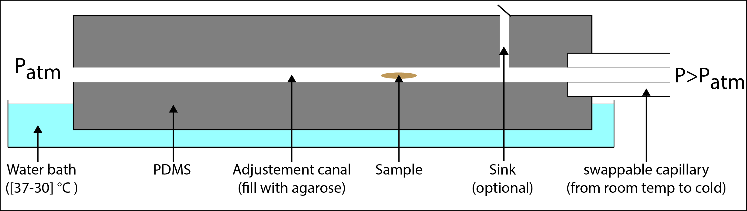
Initial setup idea
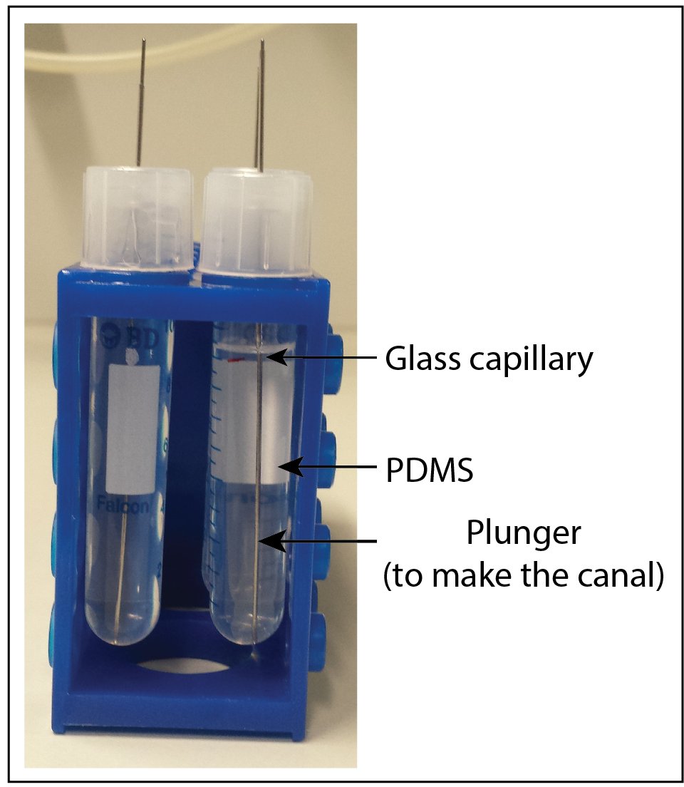
Making of the canal
First attempt
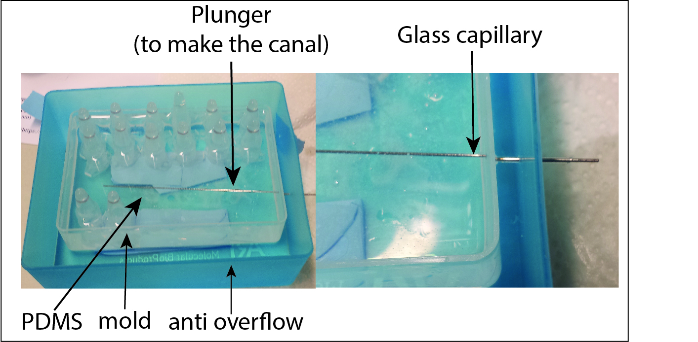
Canal preparation
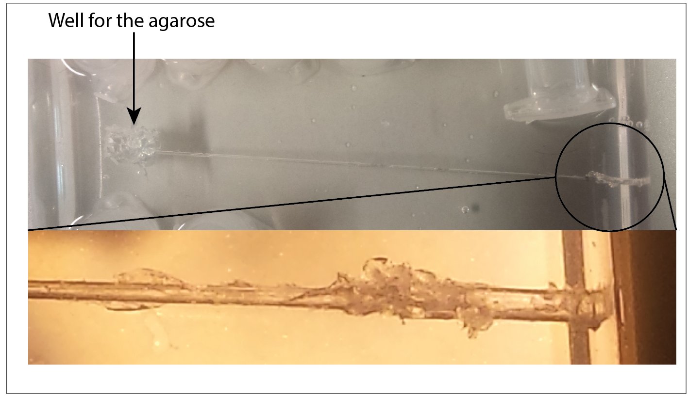
Canal preparation after the removal of the plunger
Because of the double surrounding wall around the pdms the extraction of the glass capillary was impossible and it brokes. Once the entrance is full of glasses pieces the canal become unusable
Second attempt
Canal preparation
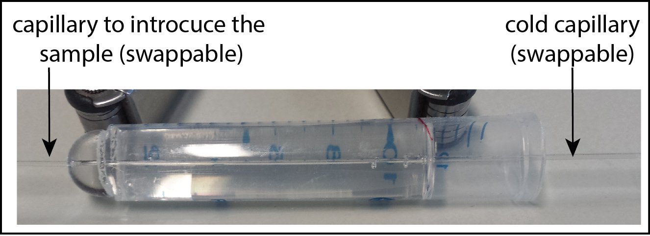
Canal preparation after the removal of the plunger
The second version of the canal is promising but due to the lake of time I only could try to mount two or three samples, unsuccessfully. Pouching the sample in the cold capillary seems more efficient than sucking it in.
High tech pressure generator

Not so good, a very slight movement of the syringe piston is equivalent to the all volume of the capillary. I think it can be master but will require quit a lot of practice
That being said
If you have at your disposal the computers, the softwares and the people that knows how to use them why bother, just go full computer science approach
1.4 Zebrafish larvae blood system imaging (Light sheet LZ. 1) and reconstruction (Multiview reconstruction)
1.4.1 Sample Preparation
We used 2dpf zebrafish embryo: Casper Tg(kdrl:GFP) expressing vascular-specific GFP labeled protein.The zebrafish was anesthetized with tricane (200µg/mL) and embedded into capillary filled with 1.5% agarose containing tricane and Beads: (Estapor® Fluorescent Microspheres 1:40000).
1.4.2 Data acquisition and processing
To investigate vein structure we used Zeiss LZ.1 Light sheet microscope. In order to image whole fish, image was acquired with 5 separate (semi-manually selected) tiles function (Fig A), 20 x obj lens, two sides illumination, one side detection and multiview function - 6 angles (Fig B). Data Processing Procedure: 42GB data was analysed with use of Reconstruction of Multiview Microscopy Data (ImageJ plugin developed by Stephan Preibisch). For registation we used beads based system followed by deconvolution and fusion (fiji plugin fiusion). For 3D animation we use Fiji plugin 3D multiview. Because of problems with huge data handling size of the image was reduced 2x.

Special thanks to Stephan Preibisch, Michaela Mickoleit, Jaroslav Icha, Olivier Burri, Kirti Prakash and Daniele Soroldoni,
The circulatory system 3D reconstruction:
Summary
Team members
Eric Edsinger
Wioleta Dudka-Ruszkowska
Thomas Pujol
Hannah Barthel

Kei Murata
Local Guides

Jaroslav Icha
Stephan Preibisch