Camera Laser Synchronization
Principle of operation
We assume that the camera is controlled by the computer via the API or other means and that it is configured such that one of its IO pins reports the integration interval. We will call this signal CINT. This pin is at 0V when not integrating and +5V when integrating. Depending on the camera model this can be reversed.
We assume that the laser has a digital IO port for binary control of intensity. We will call this signal LT. The laser illumination is then synchronized to the camera integration interval by generating the appropriate LT signal according to the incoming CINT signal. Two variables can be adjusted: delay and duration. Delay is how many microseconds separate the start of acquisition and the switching of the laser to on state. And duration is, well, how long in microseconds the laser remains on.
This parameters are sent as serial commands to the Arduino. For example, sending the following string: 'l=0,d=1000' sets the delay to zero ms and duration to 1000 mus = 1 ms.
Arduino Wiring
Rule zero of electronics: check your wirings several times, and in different ways, before powering up, there is no undo! When it's burned it's burned!
In the following, inputs and outputs are relative to the Arduino:
-
Camera pins:
- pinCSB -> Camera SYNC-B/Strobe pin (input)
-
Laser pins:
- pinLT 4 -> Laser Trigger (output)
Below is an overview diagram of the very simple wiring needed:

It is often the case that the internal camera/laser electronics are protected against electronic noise or damage by optocouplers. Optocouplers are essentially an optical form of galvanic isolation: it's an optical bridge that lets the signal go through without any current flow. Such a device needs electric current to function, and by definition this current cannot come from the camera/laser itself otherwise that would defeat the purpose of the optocoupler... To cut a long story short, you need to check whether the IO interface of the camera/laser needs to be supplied with DC current (most likely +5V). In any case you will also need to connect the GND (ground) to your 0V on the Arduino. For that you can use the +5V and 0V GND pins of the Arduino. It is a general rule that all grounds of communicating devices to be shorted together.
Rule one of digital electronics: when in doubt about the amount of current sinked or sourced by a pin and about tolerances, it is a good idea to 1) read the manual again and check how much an output pin can source, and what is the impedance of an input pin, 2) to add a resistor (200 Ohm) in series to limit current flow, just in case...
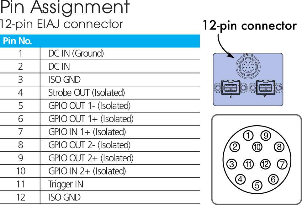
Camera Wiring
Here we detail how to use the synchronization system for the SonyXCD cameras. As explained above, and as shown in the diagram below, most cameras IO interfaces have an optocoupler - thus you have to connect GND pins to ground and DC IN pins to +5V.
This distracting detail aside, the really interesting pin is STROBE OUT which is our CINT pin and which tells us when the camera is acquiring. SonyXCD cameras output 0V when acquiring and +5V when not. This is different from Retiga-SRV cameras for example that output the opposite signal.
Laser Wiring
Wiring the laser is usually much easier, you just need a diftal IO pin that gives access to a binary control of the laser. For example, for the Coherent CUBE lasers this is called "digital enable".
Arduino Sketch
Below is the current version of the Arduino sketch:
// OpenSPIM laser/camera synchronization based on Arduino
// Loic Royer

// The principle of operation is simple:
// We assume that the camera is controlled by the computer via the API
// or other means and that the CINT signal reports the integration time
// interval. In other words the CINT pin on the camera tells us when the
// camera is aquiring (excluding the read-out time).
// On the laser side, we assume that the laser is in pulse mode.
//
// The laser is then controlled in a "slave" mode. This program synchronizes
// the laser to the camera aquisition.
// Two variables can be adjusted via a simple serial protocol: delay and duration.
// Delay is how many microseconds between start of aquisition and laser on have elapsed,
// and duration is, well, how long the laser is on in microseconds.
// sending the following string: 'l=0,d=1000' sets the delay to zero ms
// and duation to 1000 mus = 1 ms

// in the following, inputs and outputs are relative to the arduino
// Camera pins:
#define pinCINT 2// Camera integration signal pin (input)

// Laser pins:
//Important: In the case of the Coherent laser CUBE system,
// the control box BNC connector has an input impedance of 2.2 K ohm.
// The laser SMB connector has an input impedance of 50 ohm.
// --> This means that a the same resistor value have to be put in series between
// the pin and the connector on the laser.

#define pinLT 4 // Laser Trigger pin

// Debug: led pin 13
#define pinLED 13

// Parameters:
unsigned long delaytime=0;
unsigned long duration=5000;


// We define what is INT and NOINT for the camera:
#define INT HIGH
#define NOINT LOW

// We define what is LON and LOFF for the laser:
#define LON HIGH
#define LOFF LOW

// Monitored pin state:
volatile int state = NOINT;

// Working variables:
volatile unsigned long starttime;
volatile boolean pause=false;


void setup()
{
  Serial.begin(115200);
  Serial.println("OpenSPIM ARDUSYNC> Connected!");

  // Set up pin modes:
  //pinMode(pinCT, OUTPUT);
  pinMode(pinCINT, INPUT);
  pinMode(pinLT, OUTPUT);
  pinMode(pinLED, OUTPUT);
  digitalWrite(pinLT, LOFF);
  digitalWrite(pinLED, LOW);
  Serial.println("OpenSPIM ARDUSYNC> pins configured!");

  //Attach the interrupts:
  // Interrupt 0 is on DIGITAL PIN 2!
  // Interrupt 1 is on DIGITAL PIN 3!
  // Arduino Mega has an additional four: numbers 2 (pin 21), 3 (pin 20), 4 (pin 19), and 5 (pin 18).
  attachInterrupt(0, stateChange, CHANGE);
  Serial.println("OpenSPIM ARDUSYNC> interrupts attached!");

}

void loop()
{
  if(Serial.available()>0)
  {
    pause = true;
    while((delaytime=serReadInt('l'))<0);
    while((duration=serReadInt('d'))<0);
    Serial.println("OpenSPIM ARDUSYNC> Received parameter update.");
    Serial.print("OpenSPIM ARDUSYNC> delaytime=");
    Serial.print(delaytime);
    Serial.print(" duration=");
    Serial.println(duration);/**/
    pause = false;
  }
}

void stateChange()
{
  if(pause) return;
  //Serial.println("change!");
  //Serial.println(micros()-starttime);
  state = digitalRead(pinCINT);
  if(state==INT)
  {
    delaymicro(delaytime);
    digitalWrite(pinLT, LON);
    starttime = micros();
    digitalWrite(pinLED, HIGH);
    delaymicro(duration);
    digitalWrite(pinLT, LOFF);
    digitalWrite(pinLED, LOW);
    //Serial.println("high");
  }
  else if(state==NOINT)
  {
    digitalWrite(pinLT, LOFF);
    digitalWrite(pinLED, LOW);
    //Serial.println("low");
  }
}


// Helper functions are below:

void delaymicro(long microseconds)
{
  if(microseconds==0) return;
  if(microseconds>16383)
  {
    delay(microseconds/1000);
    delayMicroseconds(microseconds%1000);
  }
  else
  {
    delayMicroseconds(microseconds);
  }
}

boolean messageStart(char id)
{
  int i, serAva;                          // i is a counter, serAva hold number of serial available
  char inputBytes [7];
  if (Serial.available()>=2)               // Check to see if there are any serial input
  {
    delay(5);                              // Delay for terminal to finish transmitted
    // 5mS work great for 9600 baud (increase this number for slower baud)
    for (i=0; i<2; i++)               // Load input bytes into array
      inputBytes[i] = Serial.read();
    inputBytes[2] =  '\0';                 // Put NULL character at the end
    //Serial.println(inputBytes);
    if(inputBytes[0]==id && inputBytes[1]=='=')
    {
      return true;
    }
  }
  return false;
}

long serReadInt(char id)
{
  //Serial.println("OpenSPIM ARDUSYNC> waiting for parameter id");
  while(!messageStart(id));
  //Serial.println("OpenSPIM ARDUSYNC> correct parameter id received");

  int i, serAva;                          // i is a counter, serAva hold number of serial available
  char inputBytes [7];                    // Array hold input bytes
  char * inputBytesPtr = &inputBytes[0];  // Pointer to the first element of the array

  if (Serial.available()>0)               // Check to see if there are any serial input
  {
    delay(5);                              // Delay for terminal to finish transmitted
    // 5mS work great for 9600 baud (increase this number for slower baud)
    serAva = Serial.available();           // Read number of input bytes
    for (i=0; i