From OpenSPIM
Configuring µManager for µOpenSPIM
This site provides guidance on how to configure µManager so that an OpenSPIM can be operated using µOpenSPIM. Here one can learn how a working .cfg file is created, how multiple cameras are added to µManager and how an ArduinoUNO board has to be configured. Because every OpenSPIM system is typically equipped with different devices, it should be kept in mind that all step by step guides are written with respect to the X-OpenSPIM currently operating in the Tomancak lab.
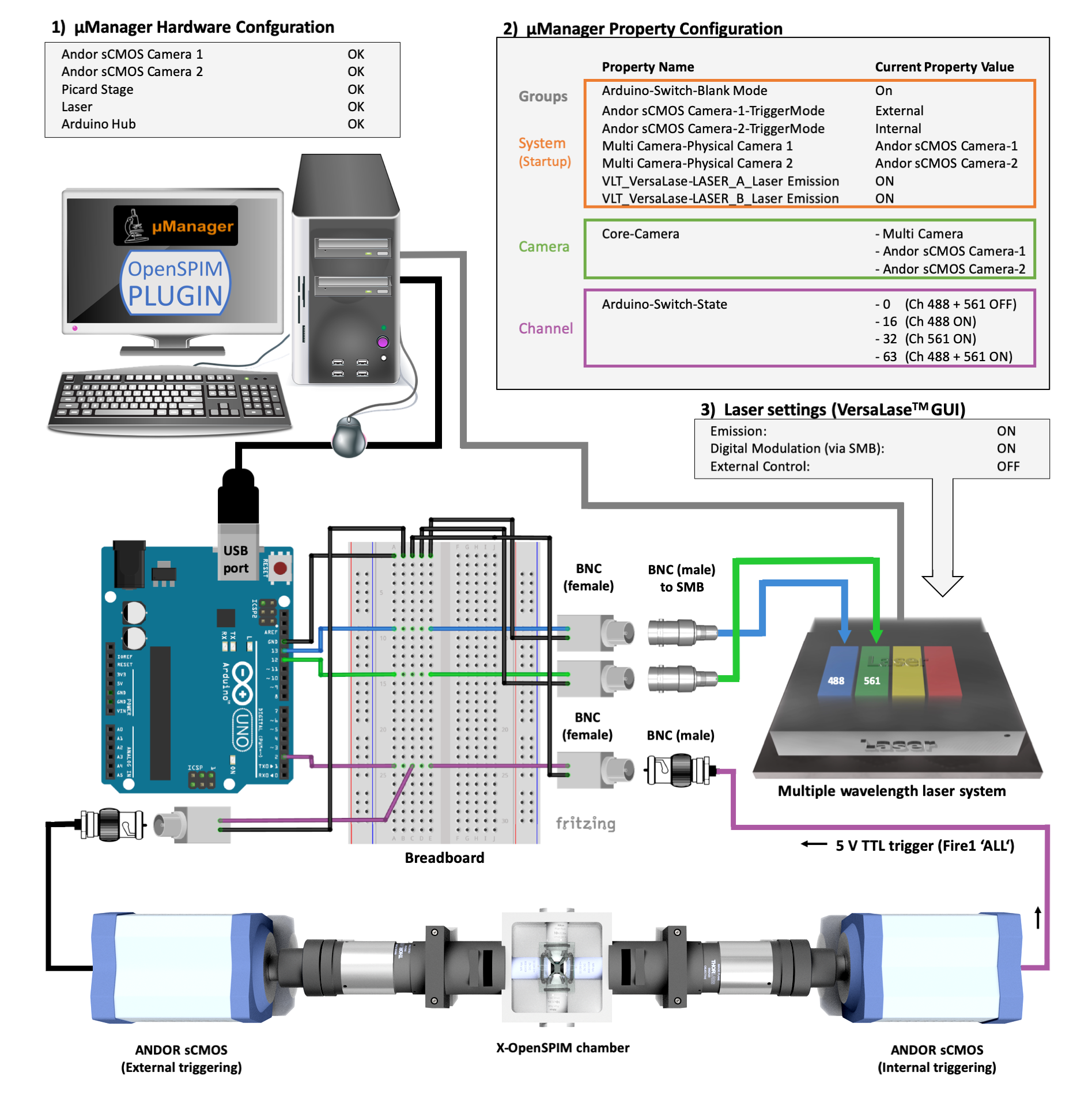
Take a look at the figure below, to quickly get an idea how the different devices are wired in the described X-OpenSPIM. The system is equipped with an ArduinoUNO. Its full circuit is shown schematically. Also necessary settings specified in µManager are also shown. Note that the Camera and Channel Groups are optional.
Creating a working .cfg file using µManager's Hardware Configuration Wizard
The following video shows how a working .cfg file was created from scratch for the following X-OpenSPIM using µManager's Hardware Configuration Wizard.
Regarding the Picard USB 4D-Stage, make sure that the "StepSize" for the X-, Y-, and Z-Stage is set to the precise value of 1.524 and also the "Max" value (maximum stepper motor range) is set to 8839 as show in the video above.
Configuring multiple cameras in µManager (X-OpenSPIM)
The following step by step guide and example video below demonstrate how to configure two sister cameras (2x Andor sCMOS Neo 5.5) in µManager to function as a single logical camera (Multi-Camera).The configuration is facilitated by the fact that both cameras are of the same type.
-
Step 1: Because both Andor cameras use the same device adapter, they can be added and named through the “Hardware Configuration Wizard” by selecting successively the “AndorSDK3” option within the folder of the same name from the list of available devices. Thereby the camera, which is initially added, should be considered the “slave” camera, whereas the second camera becomes the “master”. In case the two cameras are not of the same type, they must at least have the same width, height and pixel type properties.
-
Step 2: Use the “Hardware Configuration Wizard” to add the “Multi Camera” option, which is also located in the device list and can be found within the “Utilities” folder. Complete and save the “Hardware Configuration Wizard” comprising all other hardware components including lasers, 4D-stage and the ArduinoUNO board.
-
Step 3: Create a new “Group” within µManager’s configuration settings named “System”. This step is necessary to specify the physical camera properties. To do so, one has to go into the Group Editor by pressing the Group “Edit” button and tick the Multi Camera-Physical Camera 1 and Multi Camera-Physical Camera 2 from the Property Name list. Furthermore, the “Core-Camera”, “Binning” and “TriggerMode” has to be added for both cameras and confirmed with OK.
-
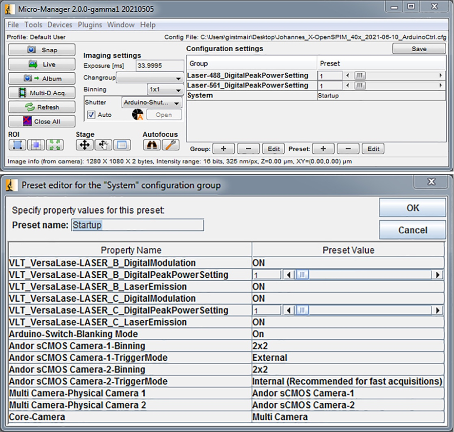
Step 4: Now is the time to edit all preset values of our newly created “System” group. Press the ”Edit” button of the preset panel. In there one can specify the Andor sCMOS Camera-1 as Multi Camera-Physical Camera 1 and Andor sCMOS Camera-2 as Multi Camera-Physical Camera-2. Additionally, the “TriggerMode” of Camera-1 (the ‘Slave’) has to be set to “External” and of Camera-2 (the ‘Master’) to “Internal (Recommended for fast acquisition)”. Subsequently we recommend to set both Cameras to 2x2 binning. All above mentioned preset values are shown in the figure below.
-
Step 5: Furthermore, we advise to follow µManager’s “Multi-Camera” recommendations and set the preset name to “Startup” as this will automatically set all Properties within the “System”-Group to any given preset value during µManager’s startup. At this point the configuration settings for the two cameras are completed and can be saved.
-
Step 6: Finally, the “Multi Camera” of µManager’s Core Camera Utility has to be selected in the Device Property Browser before a single multi-channel image (1 channel per camera) can be acquired. To shorten this step, we added another group by selecting the Utility “Core Camera”. This allowed us to quickly switch between Camera 1, Camera 2 and Multi Camera within the “Configuration Settings”.
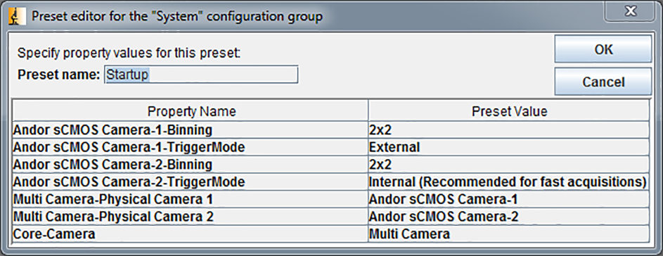
Figure 2 - Multi camera “Startup” preset values of the newly created “System” configuration group in µManager.
For multi camera imaging we recommend using a decent acquisition computer. E.g., we use a HPZ820 workstation with multiple processors and, notably, found that enabling the non-uniform memory access (NUMA) in the BIOS greatly improves image acquisition stability.
Pixel size calibration
It is also important to calibrate your Pixel Size correctly. To do this in µManager go to Devices > Pixel Size Calibration and specify the Pixel Size (µm). Before you can OK, you have to select at least one of the devices from the "Property Name" table, e.g. Core-Initialize. Now click OK and save/overwrite the current configuration file.
If you don't know the correct Pixel Size value for your OpenSPIM system check:
- the Pixel Size of your camera chip
- the magnification of your detection objective (e.g. 10x, 20x, 40x etc.)
- if the detection axis is equipped with any other demagnifying lenses (e.g. C-mount) or zoom optics. In case of the described X-OpenSPIM, the camera mounts & adapters comprising a tube lens (ITL200, Thorlabs), a U-TV1x video camera adapter (projection lens) and a U-CMAD3 video camera mount adapter retain a 1x magnification.
Once you gathered the information the following formula can be used:
+++++++++++++++++++++++++++++++++++++++++++++++++++++++++++++++++++++++++++++++++++++++++++++++++++++++++++++++++++++++
Image Pixel Size = Camera Pixel Size x Binning / Magnification of the Detection Objective x Camera Mounts x Zoom Optics
+++++++++++++++++++++++++++++++++++++++++++++++++++++++++++++++++++++++++++++++++++++++++++++++++++++++++++++++++++++++
As an example: Our two Andor sCMOS Neo 5.5 cameras have 6.5 µm pixels and the X-OpenSPIM is equipped with 40x detection objectives (CFI Apochromat NIR 40X W, Nikon). Camera mounts retain a 1x magnification and there are no additional zoom optics installed into the detection axis.
Therefore we have a Image Pixel Size of 6.5 x Binning / 40 x 1 x 1, which equals a Pixel Size value of 0.1625 µm. We don't worry about the Binning as µManager is taking this into account automatically.
Setting up an ArduinoUNO microcontroller in µManager for Camera-Laser synchronization
The following steps depict how an ArduinoUNO board can be configured to enable hardware-controlled triggering of two laser lines (in our case a 488 and 561 laser; see also Figure 23).
If one is not yet familiar with µManager’s Hardware Configuration Wizard, its Device Property Browser and how to create Configuration “Groups” and “Presets”, we recommend first reading through µManager’s Configuration Guide.
You can also watch the video below to see how an ArduinoUNO board is configured for camera-laser synchronization in an OpenSPIM in the same way as described below.
-
Step 1: Download and install the open-source Arduino UNO software (IDE:).
-
Step 2: USB-connect the Arduino board to your acquisition computer and upload the Arduino UNO firmware source code via a blank sketch window to the board. The firmware source code can be found e.g., on the µManager website under the following link.
-
Step 3: The laser itself has to be set into the correct state in order to receive the digital trigger signal from the Arduino board. The VersaLase laser system offers several trigger modes (analogue modulation via BNC or RS232, external triggering via BNC and digital modulation via SMB connectivity). In order to use the available SMB connectivity, the VersaLase settings have to be set to emission and digital modulation “ON”, while External control has to be set to “OFF”. Initially, this has to be done and checked within the VersaLase GUI software provided by the company.
-
Step 4: Run µManager’s “Hardware Configuration Wizard” (Toolbar > Devices) and choose to modify your current µManager or create a new configuration file. Then select the “Arduino” folder from the Available Devices list and add the “Arduino-Hub” from within. Provide the correct “Port value”, which can be looked up in the Device Manager’s Ports list of Windows, where the connected Arduino UNO is listed. In the “Pre-Initialization Properties” set the “BaudRate” to ‘57600’ and the “Verbrose” to ‘0’. In the “Peripheral Devices” setup step, select the “Arduino-Switch” and “Arduino-Shutter” and press “OK”. Make sure that the “Arduino-Hub”, “Arduino-Switch” and “Arduino-Shutter” are listed in µManager’s “Installed Devices”. During the subsequent steps of the “Hardware Configuration Wizard” select the “Arduino Shutter” as the “Default Shutter”.
-
Step 5: After the “Hardware Configuration Wizard” is completed, a new group should be created within µManager’s “Configuration Settings”, called “System”. In case this group already exists, due to the previous multi camera steps, simply select the group and press “Edit”. Within the Group Editor select the following features from the Property Name list and add them: “Arduino-Switch-Blanking Mode” “VLT_VersaLase-LASER {A-D} LaserEmission” Confirm by pressing “OK”, and select the newly created “System”-Group. Then specify the “Current Property Value” for all previously selected devices by pressing the Preset-”Edit” button. Set the “Arduino-Switch-Blanking Mode”, the “VLT_VersaLase-LASER {A-D} LaserEmission” as well as the “VLT_VersaLase-LASER {A-D} DigitalModulation” to “ON” and press “OK”. As already mentioned previously in the Multi-Camera section, we recommend changing the preset Name to ‘Startup’. This will automatically set all properties within the “System”-Group to the given preset values whenever µManager is started. In case the “System” Group with its “Startup” presets is not created, the “Property Values” have to be set correctly in the “Device Property Browser” every time µManager is started. As shown in the figure below, one can combine the Multi Camera property settings and presets for Binning and the camera triggering settings. We advise to create an additional group for each laser line (DigitalPeakPowerSetting), which can be used to control the digital peak power of both laser lines.
-
Step 6: (Optional) To acquire images with µManager’s “Multi-Dimensional Acquisition” (MDA) we recommend creating another “Group” called “Channels” in which the “Arduino-Switch-State” has been selected. This allows to toggle the digital output pattern across Pin-8 to Pin-13, which can be used in the MDA as a channel. It is useful to get familiarized with the digital output pattern to better understand how pins 8-13 are switched using single number values from 0-63 as described at the Arduino µManager website. In our example we will toggle between pin 13 and pin 12 with the Arduino-Switch-State values 16 and 32 respectively. The figure below depicts how Pin-13 and Pin-12 are wired to control the two laser shutters, 488 and 561 respectively.In the same way another "Group" can be created and e.g., named "Camera" whereby the "Core-Camera" can be selected to quickly toggle between MultiCamera and the two sister cameras (Camera 1 and Camera 2) respectively using µManager's group panel.
-
Step 7: Make sure the digital outputs of Pin-13 to Pin-8 of the Arduino board are correctly triggered by the digital exposure signal of the sCMOS “master” camera, which has to be wired to the Pin-2 digital input on the Arduino UNO board as shown in the figure below. The trigger mechanism of a sCMOS camera is typically based on the digital exposure output of the “master” camera but there are several options how the synchronization of the camera with an Arduino board can be achieved. E.g., there are different FIRE output cables (such as Fire 1, Fire ALL, Fire n, et cetera) for some sCMOS Andor cameras), which can give distinctive trigger signals and depend among others things on the activation of rows on the camera’s sensor chip in case the camera uses a rolling shutter instead of a global shutter. We used the output cable labelled “FIRE”. In case an Andor camera is used, more information can be found at andor.oxinst.com under the following link. After µManager’s Arduino Properties have been configured as described above and the sCMOS camera is wired to the Arduino UNO board and set into a state of exposure, e.g., by going “Live”, then the corresponding digital output pins (Pin-8 to Pin-13) will provide an approximate 5V value when measured. Make sure to test the 5V digital outputs prior to connecting them to any device. This can be done e.g., by using a voltmeter, oscilloscope or simply by making LED lights go on.