Installing illumination axis on the optical breadboard Part 2
After a rough alignment of the laser you can continue with the installation of the refractive optics.
Assembling the beam expander
The purpose of this simple telescope is to expand the output diameter of the laser from 1 mm to 2 mm. It is accomplished using a magnification of 0.5x.
Install the first lens of the beam expanding telescope in it's proper place
Objects needed
- 1x Ø1/2" f = 25 mm spherical lens assembly on it's rail carrier
- 1x measuring (length) device like a ruler or measuring stick/tape
Tools needed
None
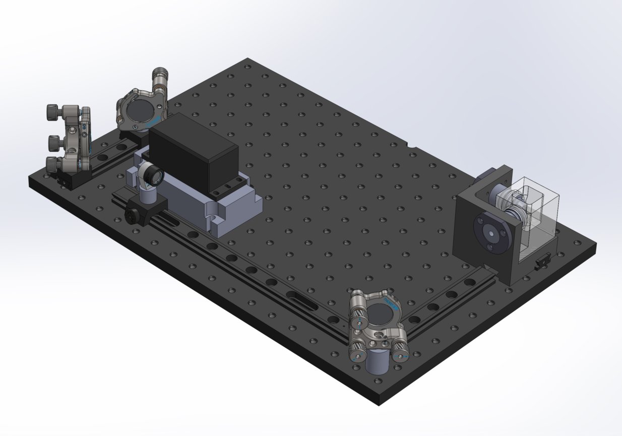
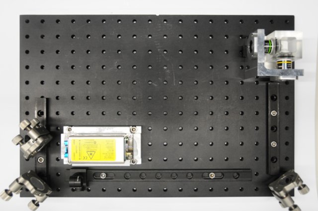
How and where to install the beam expander on the rail system
Put the Ø1/2" f = 25 mm spherical lens assembly on it's rail carrier on to the 300 mm dovetail rail near the laser and two 1/2" mirror assemblies with the tightening knob facing away from the laser and the lens facing the 1" mirror in the direction of the arrow on the lens housing. Position it between 50 to 75 mm away from the last Ø1/2" mirror surface (it doesn't really matter so much as how far away the first lens is because the entry and exit beams of the beam expander telescope system will be parallel, not focused or divergent), and tighten the tightening knob so that it doesn't move along the dovetail rail.
|
|
Install the second lens of the beam expanding telescope in it's proper place
Objects needed
- 1x Ø1/2" f = 50 mm spherical lens assembly on it's rail carrier
- 1x measuring (length) device like a ruler or measuring stick/tape
Tools needed
None
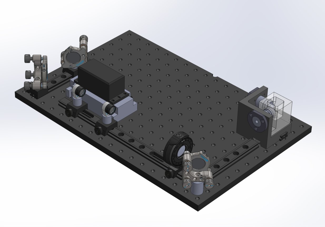
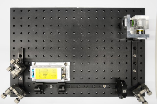
How and where to install the beam expander on the rail system
Put the Ø1/2" f = 50 mm spherical lens assembly on it's rail carrier on to the 300 mm dovetail rail near the laser and behind the first Ø1/2" f = 25 mm spherical lens assembly in relation to the direction of the light path with the tightening knob facing away from the laser and the lens facing the 1" mirror in the direction of the arrow on the lens housing. Position it about 75 mm away from the first Ø1/2" f = 25 mm spherical lens assembly. Use a business card or paper to check the beam diameter from the exit of the second lens to the Ø1" mirror to see if the light deviates (either focuses or diverges). Adjust the distance between the two lenses until the beam is uniformly the same diameter all the way to the Ø1" mirror and illumination objective. Then tighten the tightening knob on the second lens so that it doesn't move along the dovetail rail.
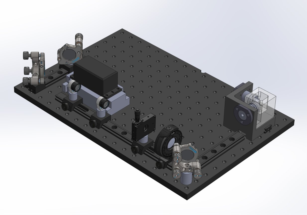
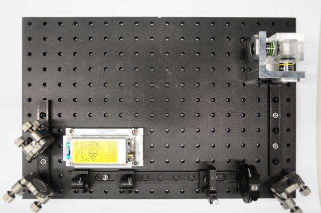
Installation of beam expander

|

|
Install the cylindrical lens in it's proper place
The cylindrical lens needs to be installed it such a way that it focuses the expanded beam to a thin horizontal line onto the Ø1" mirror.
Objects needed
- 1x Ø1" f = 50 mm cylindrical lens assembly on it's modified rail carrier
- 1x measuring (length) devise like a ruler or measuring stick/tape
Tools needed
None
How and where to install the cylindrical lens assembly on the rail system
Install the cylindrical lens assembly on the 300 mm dovetail rail around 50 mm from the Ø1" mirror with the lettering of the rotating index mount facing the reflective surface of the mirror. To adjust the focus of the cylindrical lens, shine the laser at a very low intensity through the beam expanding telescope and into the cylindrical lens. Then move the cylindrical lens assembly along the axis of the 300 mm dovetail rail until you find the thinnest horizontal line in the middle of the Ø1" mirror. Then tighten the tightening knob so that it doesn't move along the dovetail rail.
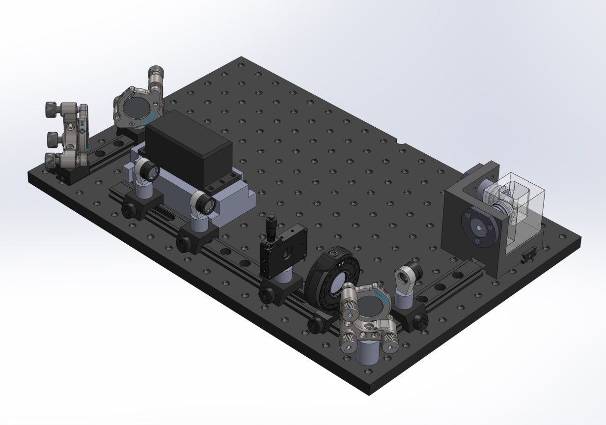
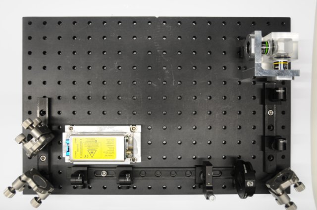
Installation of cylindrical lens
|
|
Install the vertical slit in it's proper place
Objects needed
- 1x vertical assembly on it's rail carrier
- 1x measuring (length) devise like a ruler or measuring stick/tape
Tools needed
None
How and where to install the vertical slit assembly on the rail system
Install the vertical slit assembly on the 300 mm dovetail rail 50 mm behind the cylindrical lens assembly on the other side from the mirror. You can find out where to lock it in place by looking for back reflections from the mirror through the cylindrical lens on to the closed vertical slit. Moving the slit back and forth on the dovetail rail you will find the thinnest/sharpest line of the back reflections.
Installation of vertical slit
|
|
Assembling the telescope
The purpose of this simple telescope is to make the back focal plane (BFP) of the water dipping illumination objective conjugate to the 1" mirror. It is accomplished using a magnification of 2x. It also makes adjusting the light sheet much easier than mounting the cylindrical lens directly to the back of the objective, by adjusting the mirror you adjust where the light sheet is at by a turn of a knob (or three...).
Note 1: it is important that the lenses of this telescope are placed at correct distances from the cylindrical lens and the objective. The beam has to be focused to a horizontal line exactly on the BFP of the microscope objective. Only this way a thin light sheet with a constant height will be generated after the objective.
Note 2: if you are using a different objective and you are not sure about the correct distances, you can use the following trick: remove the cylindrical lens and install the second lens of the BFP. Adjust the distance between the lens and the objective so that a perfectly collimated round beam exits the objective. This is the case only if the lens is exactly one focal length from the BFP of the objective.
Install the first lens of the BFP telescope in its proper place
Objects needed
- 1x Ø1/2" f = 50 mm spherical lens assembly on it's rail carrier
- 1x measuring (length) devise like a ruler or measuring stick/tape
Tools needed
None
How and where to install the telescope on the rail system
Put the Ø1/2" f = 50 mm spherical lens assembly on it's rail carrier on to the 150 mm dovetail rail 50 mm from the 1" mirror, the best way to do this is with a ruler or measuring stick/tape.
|

|
Install the second lens of the BFP telescope in its proper place
Objects needed
- 1x Ø1/2" f = 25 mm spherical lens assembly on it's rail carrier
- 1x measuring (length) device like a ruler or measuring stick/tape
Tools needed
None
How and where to install the telescope on the rail system
Put the Ø1/2" f = 25 mm spherical lens assembly on it's rail carrier on to the 150 mm dovetail rail 75 mm away from the first lens of the BFP telescope, between it and the water dipping objective.
Installation of telescope

|
|