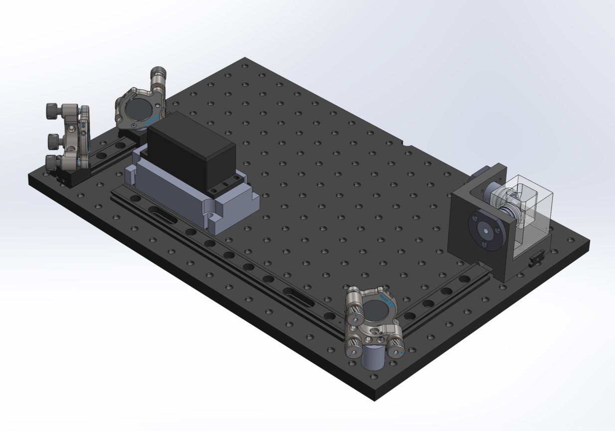
Installing illumination axis on the optical breadboard Part 1
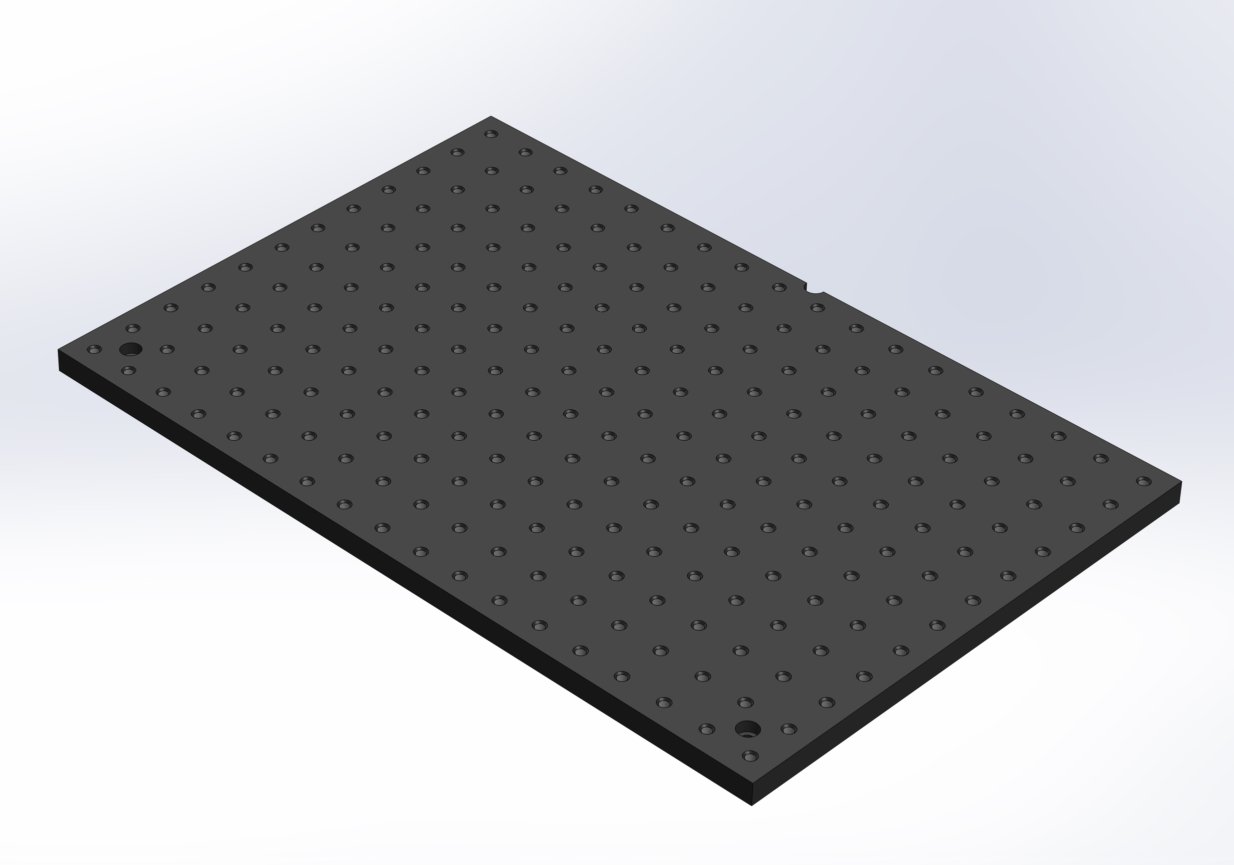
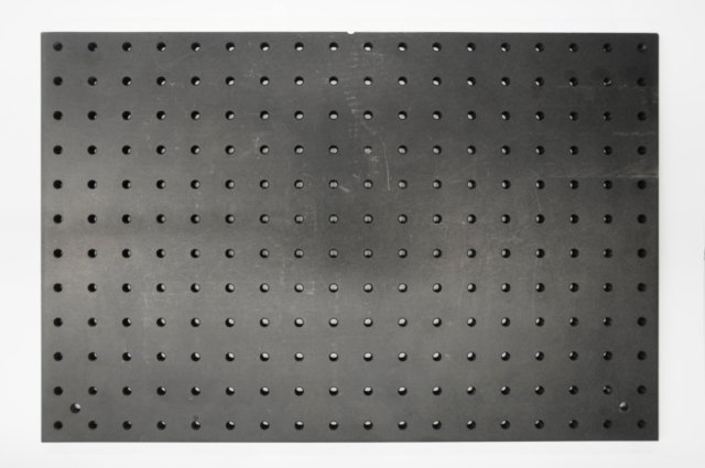
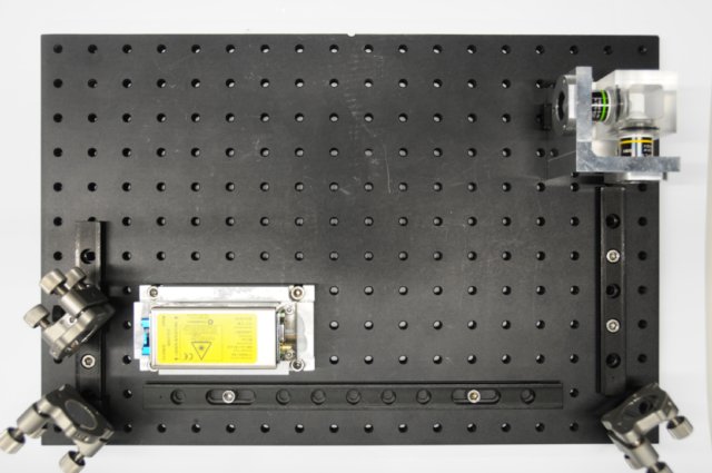
The optical breadboard (ThorLabs Part # MB3045/M) has a depth of 300 mm and a width of 450 mm, with a grid of 12 x 18 M6 threaded holes spaced 25 mm apart from one another. We will use a coordinate system similar to a spreadsheet (like OpenOffice Calc or Microsoft Excel) to make it easier to know where each component and capscrew is positioned. Starting with A1 in the upper left corner (as seen in the images), and ending with R12 in the lower right
Please also forgive the confusion about the Youtube videos and their corresponding images below, the documentation was done in two different locations months apart from each other and small design changes happened in between.
Install 1" mirror assembly and its spacer post
Objects needed
- 1x POLARIS-K1 1" mirror mount with mirror installed
- 1x 25 mm tall optical post/spacer with M4 thru tap through the center
- 1x ThorLabs part # SD1 - M4 to M6 adapter
- 1x M4 x 45 mm capscrew
- 1x M4 nut
Tools needed
- 1x 3 mm hex key/driver
- 1x Needle nosed pliers
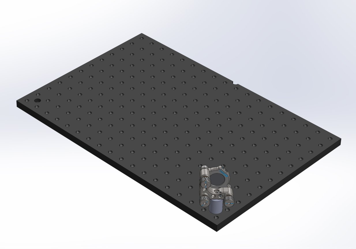
How to install the large mirror mount on the corner of the optical breadboard
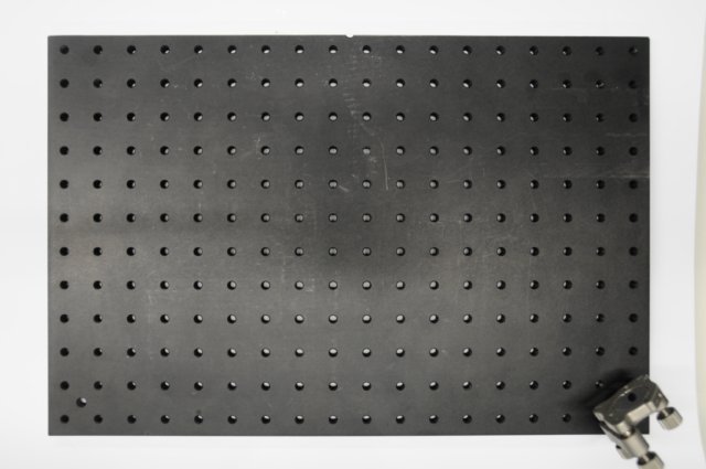
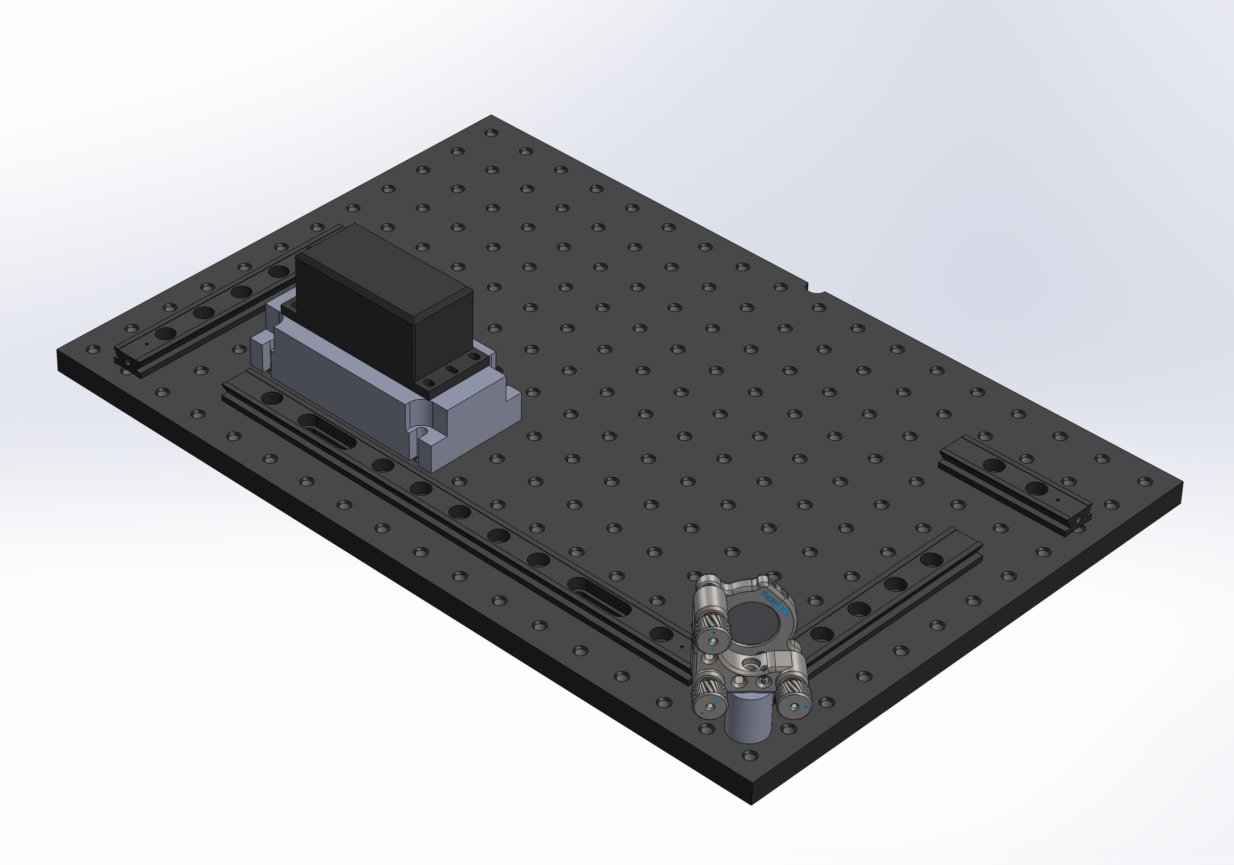
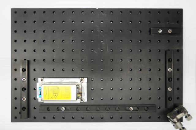
Put the M4 x 45 mm capscrew through a SD1 M4 to M6 adapter, then the capscrew/adapter assembly through the bottom side of the optical breadboard in a corner M6 thru tap. It is easy to differentiate between the thru tap and threaded hole, because the thru tap is off the usual grid between 4 threaded holes. The bottom side is the side where you can see 2 different diameters of thru tap, the larger one that stops half way through the optical breadboard is where the SD1 washer can rest.
From here on out till the completion of the installation of the OpenSPIM the furthest threaded hole juxtaposed in the opposite corner to the 1" mirror post will be called A1.
Assembly large mirror mount to optical breadboard
|

|
|
|

|
|
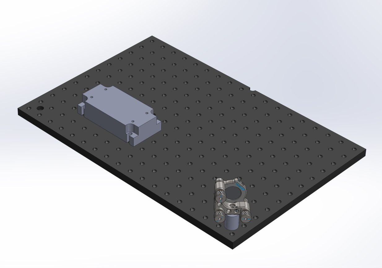
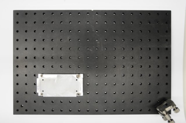
Install the CUBE laser heatsink
Objects needed
- 1x Coherent CUBE solid state laser diode
- 1x Machined metal (i.e. Aluminum) laser heatsink
- 4x M6 x 25 mm capscrews
Tools needed
- 1x 5 mm hex key/driver
How and where to install the laser with heatsink on the optical breadboard
Place the laser heatsink so that the mounting capscrew holes/notches are at D8, D10, H8 & H10 on the optical breadboard respectively. Using a 5 mm hex key/driver, screw the heatsink down to the optical breadboard using M6x25 mm capscrews.
Note that in this video the laser is already bolted onto the heatsink.
Installation of laser with heatsink on optical breadboard
|
|
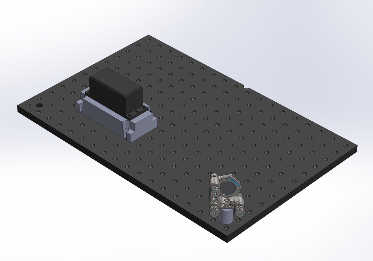
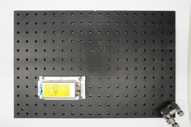
Mount the laser on the laser heat sink
Objects needed
- 1x Coherent CUBE solid state laser diode
- 1x Machined metal (i.e. Aluminum) laser heatsink (that will raise the laser beam output to 50 mm off the surface of the optical breadboard)
- 4x M4 capscrews that came with the CUBE laser with their included washers.
- 1x Heat transfer paste
Tools needed
- 1x 3 mm hex key/driver
Directions
Wear latex or nitril gloves that comfortably fit your hands! Apply heat transfer paste to the surface of the metal heat sink block where the CUBE laser will sit (everywhere between the four M4 threaded holes). Put the M4 capscrews that came with the CUBE laser through their included washers and the top of the holes in the base plate of the CUBE laser into the heatsink. using a 3 mm hex key/driver, screw the CUBE laser down onto the surface of the heatsink where the heat transfer paste is applied. Remove excess heat transfer paste with gloves on your hands!
Putting the laser on the heatsink
|
|
Mount dovetail rails onto optical breadboard
Objects needed
- 1x ThorLabs part # RLA075/M 75 mm dovetail rail
- 2x ThorLabs part # RLA150/M 150 mm dovetail rails
- 1x ThorLabs part # RLA300/M 300 mm dovetail rail
- 6x (or more) M6 x 16 mm capscrews
Tools needed
- 1x 5 mm hex key/driver
How to and where to install the dovetail rails on the optical breadboard
-
Place one of the 150 mm dovetail rails lengthwise with its ends on B6 to B12. Using the 5 mm hex key/driver, screw in 2 to 5 M6 capscrews along the length of the dovetail rail in holes B7 through B11. I personally put 2 M6 capscrews in B8 and B10.
-
Place the 300 mm dovetail rail lengthwise along row 11 between columns D and O. Using the 5 mm hex key/driver, screw in 2 M6 capscrews in the middle of the 2 long slit holes of the dovetail rail in holes F11 and M11. You can slide the position of the dovetail rail 25 mm along its long axis.
-
Place the other 150 mm dovetail rail lengthwise with its ends on Q5 to Q11. Using the 5 mm hex key/driver, screw in 2 to 5 M6 capscrews along the length of the dovetail rail in holes Q6 through Q10. I personally put 2 M6 capscrews in Q7 and Q9.
-
Place the 75 mm dovetail rail lengthwise with its ends on O3 to R3. Using the 5 mm hex key/driver, screw in 2 M6 capscrews along the length of the dovetail rail in holes P3 through Q3. I personally put 2 M6 capscrews in B8 and B10.
Assembly of dovetail rails to optical breadboard
|
|
Install both Ø1" mirror assemblies on rail system
Objects needed
- 2x Ø1" mirror assemblies on rail carriers
- 1x Optical breadboard with dovetail rail system installed
Tools needed
- None
How and where to install the Ø1" mirror mounts on the first 150 mm dovetail rail
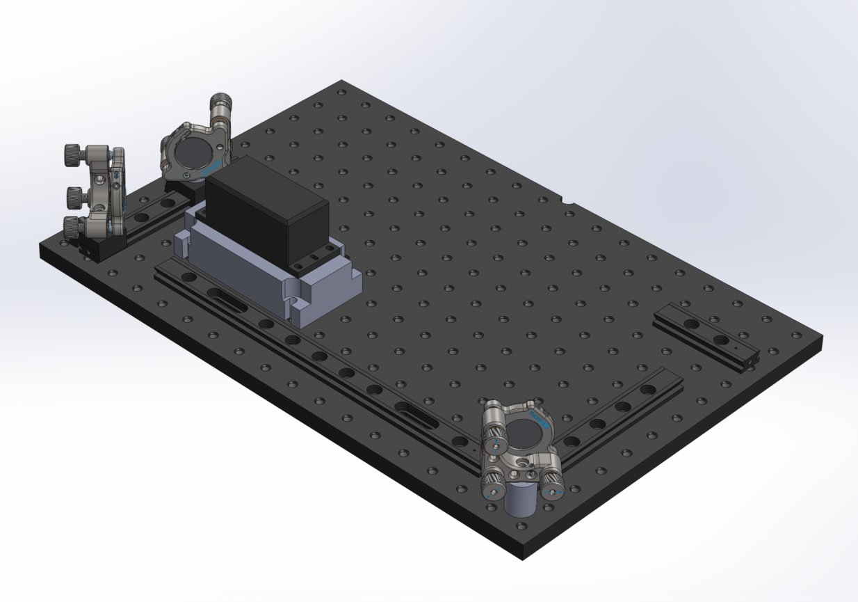
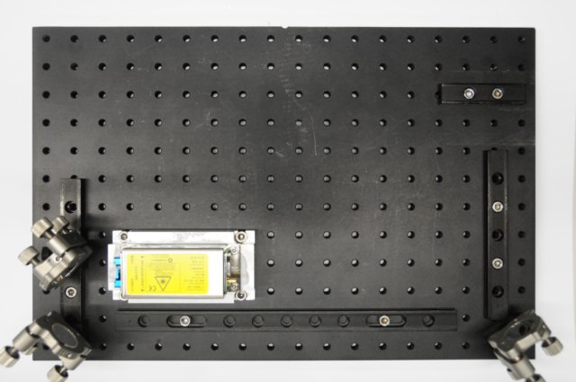
Position the two Ø1" mirror assemblies on their respective rail carriers on the first 150 mm dovetail rail so that the laser beam will be reflected along the whole rail system. The first Ø1" mirror assembly should face 45 degrees to the right of the front of the laser while the second should face 45 degrees to the left. See the images or video below for further clarification.
Make sure that the position of the horizontal adjustment screw is on the left side when looking from behind. Also, the rail carriers tightening knobs should always face out along the edge of the OpenSPIM system.
Installation of small mirror assemblies to dovetail rail system
|
|
Install the OpenSPIM chamber
Objects needed
- 1x OpenSPIM chamber assembly
- 1x Optical breadboard with dovetail rail system installed
Tools needed
- None
How and where to install the OpenSPIM chamber on the rail system
Slide the OpenSPIM chamber assembly onto the 75 mm dovetail rail along the 20x detection objective axis so that the back of the 10x illumination objective is facing the Ø1" mirror mount on the stand in the corner along the second 150 mm dovetail rail axis.
Installation of SPIM chamber assembly to dovetail rail system
|
|